DISASSEMBLY OF THE VCR (Cont.)
4)
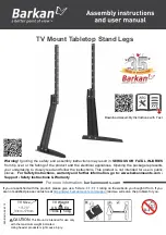
Remove the screw holding the PRISM LINK L.
5)
Release the hook B by pushing it in the direction of the arrow and remove the DOOR OPENER.
6)
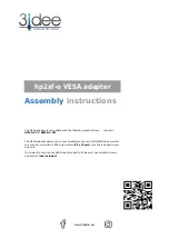
Remove the LOADING LEVER ASSEMBLY by pressing the connected section of the LOADING LEVER ASSEMBLY in the
direction of the arrows.
7)
Remove the SAFETY SPRING between the SAFETY LEVER and the CASSETTE HOLDER PLATE.
8)
Remove the RELEASE SPRING between the RELEASE LEVER and the SAFETY LEVER R.
12
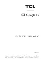
Disassembly of the top plate
Fig.17.
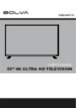
Disassembly of the cassette holder assembly
Fig.18.
Содержание TX-21GV1
Страница 34: ...cp421vbl sch 1 Wed May 19 17 22 44 1999 VIDEO BLOCK DIAGRAM ...
Страница 35: ...cp421abl sch 1 Wed May 19 17 19 52 1999 AUDIO BLOCK DIAGRAM ...
Страница 36: ...cp421pbl1 sch 1 Wed May 19 17 21 31 1999 POWER BLOCK DIAGRAM ...
Страница 48: ...39 6 3 EXPLODED VIEW OF F L ASS Y 3 576 2 7 21 9 5 ...
Страница 50: ......
Страница 51: ...SCHEMATIC DIAGRAMS FOR MODELS ZEICHENERKLÄRUNG FÜR MODELL TX 21GV1C TX 14GV1C ...
Страница 52: ......
Страница 53: ......