background image

51

English

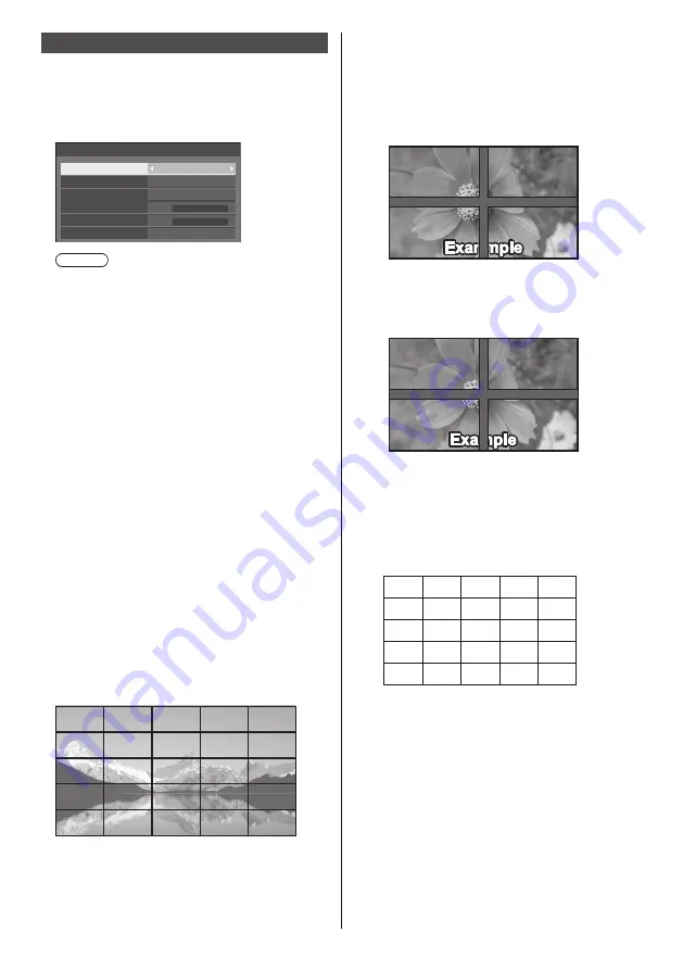
Multi display settings

1 to 5 displays can be aligned in horizontal direction and 

vertical direction respectively, and those displays are 

regarded as one group. The enlarged image is shown on 

the combined display.

[Multi display settings]- submenu screen

0

0

Multi display settings

Multi display setting

Horizontal scale

Bezel H adjustment

Vertical scale

Bezel V adjustment
Location

Off

2
2

A1

Note

● 

The settings are memorised separately for each 

input terminal.

● 

When the multi display is set to [Off], adjust to the 

same angle of view for [Position] (see page 35). 

Then, set the multi display to [On]. Again, make 

fine adjustment of the angle of view for [Position].

● 

The [Position] menu can be adjusted in the multi 

display status.

● 

The multi display mode is not available with USB 

input.


[Multi display setting]

[Off]:

The display is not divided when enlarged.

[On]:

The display is divided when enlarged.

When [On] is set, the display aspect is [16:9].


[Horizontal scale]

Set the horizontal scale in the multi display.

1 ‒ 5


[Vertical scale]

Set the vertical scale in the multi display.

1 ‒ 5

Example:
[Horizontal scale] [5] and [Vertical scale] [5] is set in 

the multi display


[Bezel H adjustment] / [Bezel V adjustment]

Adjust the area of image hidden in the joint 

horizontally and vertically respectively.

0 ‒ 100

Display example

Setting value: 0

Displays the entire image including the joint area. 

(Suitable when displaying character information 

on PC.)

Setting value: 100

Does not display the image of the joint area.  

(Suitable when displaying motion pictures.)


[Location]

Assign the multi display position.
Example:
[Horizontal scale] [5], [Vertical scale] [5]

A1 A2 A3
B1 B2 B3

C1 C2 C3

A4
B4

C4

E1 E2 E3 E4

D1 D2 D3 D4

A5
B5

C5

D5

E5

Select from A1 to A5, B1 to B5, C1 to C5, D1 to D5, 

E1 to E5. 

● 

The displayed content for setting changes 

according to the settings for the [Horizontal scale] 

and [Vertical scale].

● 

By setting [Multi display setting] to [Off], it is 

possible to check the location on the screen while 

the setting menu is displayed.

Содержание TH-84EF1U

Страница 1: ...model TH 84EF1W 84 inch model TH 75EF1W 75 inch model English Please read these instructions before operating your set and retain them for future reference This manual is common to all the models rega...

Страница 2: ...actual ones Descriptive illustrations in this Operating Instructions are created mainly based on the 84 inch model Important Safety Instructions 4 FCC STATEMENT 5 Important Safety Notice 6 Safety Prec...

Страница 3: ...ers to be connected 64 Example of network connection 64 Command control 64 Control Command via LAN 65 PJLink protocol 68 Early Warning Software 69 Multi Monitoring Control Software 69 Video Wall Manag...

Страница 4: ...ly with dry cloth 7 Do not block any ventilation openings Install in accordance with the manufacturer s instructions 8 Do not install near any heat sources such as radiators heat registers stoves or o...

Страница 5: ...FCC CAUTION To assure continued compliance follow the attached installation instructions and use only the provided power supply cord Any changes or modifications not expressly approved by Panasonic C...

Страница 6: ...of Crestron Electronics Inc Crestron Connected is the trademark of Crestron Electronics Inc Even if no special notation has been made of company or product trademarks these trademarks have been fully...

Страница 7: ...three pin mains plug for your safety and convenience A 10 amp fuse is fitted in this plug Shall the fuse need to be replaced please ensure that the replacement fuse has a rating of 10 amps and that i...

Страница 8: ...the Display vertically 84 inch model only When installing the Display vertically be sure that the Power Indicator comes to the downside Heat is generated and it may cause fire or damage to the Displa...

Страница 9: ...le make any modifications to it place heavy objects on top of it heat it place it near any hot objects twist it bend it excessively or pull it To do so may cause fire and electric shock If the power c...

Страница 10: ...unit If this is not observed the unit may drop resulting in injury Be sure to disconnect all cables before moving the Display If the Display is moved while some of the cables are still connected the...

Страница 11: ...d crystal panel will cause unevenness of the screen display resulting in malfunction Depending on the temperature or humidity conditions uneven brightness may be observed This is not a malfunction Thi...

Страница 12: ...en added and then wring the cloth dry Use this cloth to wipe the cabinet and then wipe it dry with a dry cloth Do not allow any detergent to come into direct contact with the surface of the Display If...

Страница 13: ...r Helpful Hint For frequent remote control users replace old batteries with Alkaline batteries for longer life Precaution on battery use Incorrect installation of the batteries can cause battery leaka...

Страница 14: ...it Do not hold the front surface of the liquid crystal panel Also do not hit such parts Doing so may damage the liquid crystal panel Also the panel may crack resulting in injury Eyebolt The display ha...

Страница 15: ...pplied AC cord is for this unit exclusive use Do not use this for other purposes Cable fixing Note 3 clampers are supplied with this unit Fix the cables at 3 locations using the holes for clampers as...

Страница 16: ...SERIAL IN SERIAL Input Terminal Control the Display by connecting to PC see page 21 6 LAN LAN Terminal Control the Display by connecting to Network see page 64 7 USB USB Terminal Connect the USB memo...

Страница 17: ...ect GND first then insert the connecting terminal of the connecting device in a straight manner Acquire any cable necessary to connect the external device to the system that is neither supplied with t...

Страница 18: ...lock CEC SCL SDA DDC CEC Ground 5V DC Hot Plug Detect DVI D IN terminal connection Note Video equipment and cables shown are not supplied with this unit Use the DVI D cable complying with the DVI stan...

Страница 19: ...l PC input signals that are described in Preset Signals see page 89 adjustment values such as for the standard picture positions and sizes have already been stored in this unit Computer signals which...

Страница 20: ...t Terminal Mini D sub 15P 1 6 7 8 3 9 4 5 10 15 14 13 12 11 2 Pin No Signal Name R PR CR G Y B PB CB NC not connected GND Ground GND Ground GND Ground GND Ground 5 V DC GND Ground NC not connected SDA...

Страница 21: ...computer to the Display Additional computer and cables shown are not supplied with this set Pin assignments and signal names for SERIAL Terminal 6 7 8 9 1 3 4 5 2 Pin No Signal Name NC not connected R...

Страница 22: ...ng the next command When sending a command which does not require parameter a colon is not needed If an incorrect command is sent by mistake this unit will send an ER401 command back to the computer I...

Страница 23: ...n the Sound menu to AUDIO OUT see page 37 USB terminal connection Connect the USB memory commercially available to use USB media player see page 78 Also power is supplied when a separately sold stick...

Страница 24: ...e size of a stick PC etc use a commercially sold extension cable Depending on the type of a USB memory device it may come in contact with the periphery such as a back cover and cannot be attached Use...

Страница 25: ...management function see page 47 When the power of the unit is OFF Main Power On Off button OFF No light Note Even if the display unit is turned off with the power indicator off some of the circuits a...

Страница 26: ...tion size of the screen see page 35 11 INPUT Switches input to display on the screen see page 29 12PICTURE see page 38 13SOUND see page 37 14RECALL Displays the current setting status of Input mode As...

Страница 27: ...The power plug shown at left may therefore not be the type fitted to your set When disconnecting the AC cord be absolutely sure to disconnect the AC cord plug at the socket outlet first The settings m...

Страница 28: ...page 50 Display orientation see page 56 Power ON message The following message may be displayed when turning the unit power ON No activity power off Precautions No activity power off is enabled When N...

Страница 29: ...bout 30 seconds at the end When a USB memory is not connected to the USB terminal at the time of using the USB input No external media is displayed for about 30 seconds Even when a USB memory is conne...

Страница 30: ...me level is changed While MUTE is active is displayed as a reminder after operation When the image set in No signal image settings see page 49 is displayed is not displayed after operation In ENGLISH...

Страница 31: ...nels Aspect mode Description Zoom1 Letterbox pictures with a 16 9 aspect ratio are enlarged vertically to fill the screen The top and bottom edges of the pictures are cut off Zoom2 Letterbox pictures...

Страница 32: ...l zoom mode Press RETURN to exit the mode The screen returns to the previous state just before entering the digital zoom mode and the digital zoom operation guide display disappears Press any of the f...

Страница 33: ...Picture Default Default Picture mode Normal 2 2 6500K Backlight Contrast Brightness Colour Hue Sharpness Gamma Colour temperature Dynamic contrast Colour enhancement Memory save Memory load Memory ed...

Страница 34: ...Picture mode Normal 2 2 6500K Backlight Contrast Brightness Colour Hue Sharpness Gamma Colour temperature Dynamic contrast Colour enhancement Memory save Memory load Memory edit Off Setup menu see pag...

Страница 35: ...signal PC While displaying the picture of the corresponding signal select Auto setup and press ENTER Using Remote Control Press AUTO SETUP When Auto Setup does not work Invalid is displayed Auto mode...

Страница 36: ...this happens adjust so that any such noise is minimized Over scan Turn image over scan On Off Applicable input signal 525i 525p 625i 625p 750 60p 750 50p Component Video RGB DVI D HDMI On Off Note Wh...

Страница 37: ...fault Output select Select the audio output SPEAKERS Internal speakers AUDIO OUT AUDIO OUT terminal output When AUDIO OUT is selected the other menus are greyed out and cannot be selected Audio volume...

Страница 38: ...environment where this unit is used Normal For viewing in standard evening lighting environments Dynamic For viewing in brighter environments Cinema For use in viewing tone focused pictures with brigh...

Страница 39: ...in R bias G bias B bias R gain Adjusts the white balance for light red areas 0 255 G gain Adjusts the white balance for light green areas 0 255 B gain Adjusts the white balance for light blue areas 0...

Страница 40: ...ancement Memory save Memory load Memory edit Off Dynamic contrast Gamma 2 2 Memory save see page 41 Memory load see page 41 Memory edit see page 42 1 2 3 MEMORY1 MEMORY2 MEMORY3 4 MEMORY4 5 MEMORY5 6...

Страница 41: ...a a A b c d e f g h i j k l m n o p q r s t u v w x y z _ Ok Cancel All delete Delete 6 When you finished entering the profile name select Ok with and press ENTER MY MEMORY1 0 1 2 3 4 5 6 7 8 9 a b c...

Страница 42: ...profiles select All delete 4 Select Ok with and press ENTER Memory delete Delete the MEMORY1 data Ok Cancel Renaming profiles 1 In the Picture menu select Memory edit with and press ENTER Memory save...

Страница 43: ...n When HDMI DVI is selected 60 00 Hz 74 18 MHz 1125 1080 60i 33 72 kHz Signal Cinema reality YUV RGB in select Noise reduction Signal range MPEG noise reduction V freq H freq Dot clock freq Signal for...

Страница 44: ...nal which is input from the Y connector HV sync Uses a synchronized signal on the Video HD VD signal which is input from the HD VD connector Cinema reality Faithfully reproduces videos shot with cinem...

Страница 45: ...Colour system Sets the colour system according to the signal method at VIDEO input Set this to Auto normally This automatically detects the input signal format Auto PAL SECAM NTSC NTSC 4 43 PAL M PAL...

Страница 46: ...down to change the time by 15 minutes In ENGLISH US OSD language Operating time is displayed as SAVER DURATION Periodic time Deactivated Operating time Screensaver Start Mode Interval Periodic time Op...

Страница 47: ...nsumption reduction Individual setting is not available No signal power off Enable HDMI1 power management On HDMI2 power management On DVI D power management On PC power management On Power save On Po...

Страница 48: ...turned on the power indicator lights up green Note This function may not operate depending on the video output devices PC power management DPMS function When this function is set to On it operates und...

Страница 49: ...e no signal image Images displayed for the startup image and no signal image may slightly differ from images confirmed on the computer Startup image settings No signal image settings Operate No signal...

Страница 50: ...ead Clear user image is greyed out and cannot be selected When Image select is set to User image performing Clear user image will change the setting of Image select to Default image Wobbling Automatic...

Страница 51: ...d When On is set the display aspect is 16 9 Horizontal scale Set the horizontal scale in the multi display 1 5 Vertical scale Set the vertical scale in the multi display 1 5 Example Horizontal scale 5...

Страница 52: ...every day when Everyday is set 4 Set the power On Off 5 Set the time Pressing once changes time 1 minute Pressing continuously changes time by 15 minutes 6 Set the input Date and time Set date and ti...

Страница 53: ...onfigured Select LAN setup with and press ENTER 192 168 0 8 255 255 255 0 192 168 0 1 1024 LAN setup Save DHCP Off IP address Subnet mask Gateway Port DHCP IP address Subnet mask Gateway Press to set...

Страница 54: ...V RoomView Server Edition Crestron Connected is a function to connect to a system developed by Crestron Electronics Inc which manages and controls multiple system devices connected to the network For...

Страница 55: ...be selected with single touch operation HDMI1 HDMI2 DVI D PC VIDEO USB Memory load Memory can be loaded with single touch operation Memory load see page 41 MEMORY1 to MEMORY6 MEMORY1 to MEMORY6 load...

Страница 56: ...ay orientation in the portrait setting Landscape On screen display angle is for horizontal installation Portrait The on screen display rotates anticlockwise by 90 degrees for easy view in the portrait...

Страница 57: ...Power management POWER button lock Off On On Off Off Note POWER button lock function is only for TH 84EF1U and TH 75EF1U 4 Select the item to set with For Input search and Information timing the subme...

Страница 58: ...al is interrupted even for a very short period 1 10 Sets the delay time sec Switches the input when the set time has elapsed after detecting no signal is present However if the detection period during...

Страница 59: ...Initial VOL level Adjusts the sound volume level when the unit is turned on Off It will be the sound volume level which had been set before the power of the unit was turned off On Sets your preferred...

Страница 60: ...l Note About how to reset the settings to defaults Initialization see page 63 PC auto setting Sets the operational mode of the automatic position adjustment in the Position menu Off Automatic position...

Страница 61: ...nformation timing Set up the informing manner for no signal During RS 232C controls Warning or error message sent from the display automatically During LAN controls Acquire the warning or error messag...

Страница 62: ...is displayed at the lower left of the screen when RECALL button is pressed Display duration is approx 5 seconds When current date and time is not set the clock is not displayed even when Clock displa...

Страница 63: ...nd Controller ID function settings set all the values Off so that all the buttons are enabled again Press Unit together with RETURN and hold for more than 5 seconds Shipping is displayed and the lock...

Страница 64: ...le OS Windows Mac OS Compatible Web Browser Internet Explorer 7 0 8 0 9 0 10 0 11 0 Windows Safari 4 x 5 x 6 x Mac OS Example of network connection Note To use the network function set each item in Ne...

Страница 65: ...te 8 bytes 1 byte Mode 1 Protect mode 3 Hash the following data with the MD5 algorithm and generate a 32 byte hash value zzzzzzzzyyyyy zzzzzzzz 8 byte random number obtained in step 2 yyyyy Password o...

Страница 66: ...ymbol STX 0x02 Control command ASCII character string ETX 0x03 CR 0x0d 1 byte Undefined 1 byte 1 byte Error response Error message Last terminal symbol ERR1 Undefined control command CR 0x0d ERR2 Out...

Страница 67: ...byte 1 byte Undefined 1 byte Error response Error message Last terminal symbol ERR1 Undefined control command CR 0x0d ERR2 Out of parameter range ERR3 Busy status or reception invalid period ERR4 Time...

Страница 68: ...unit s Network function is compatible with PJLink Class 1 The following operations can be performed from a computer when PJLink protocol is used Setting the Display Querying the Display status Support...

Страница 69: ...ion JBMIA below http pjlink jbmia or jp english index html Early Warning Software This unit supports Early Warning Software which monitors the statuses of devices projectors or flat panel displays con...

Страница 70: ...twork control to On see page 53 Computer Setup Disable the proxy server settings and enable JavaScript The setting procedure differs depending on the software version Please refer to description in HE...

Страница 71: ...the user name and password when the Authentication screen is displayed 4 Click OK After logged in the TOP screen of the Web Browser Control is displayed Note The password used here is the same passwo...

Страница 72: ...ge displays the Display statuses established for the items shown below Displays the type of Display Displays the firmware version of the Display main unit Network status page Click Status then Network...

Страница 73: ...ut field New password input field re enter for confirmation Button for executing password change User mode A user can change password only 1 2 3 4 Current password input field New password input field...

Страница 74: ...t the connection Adjust clock page Click Detailed set up then Adjust clock to display the Adjust clock page New date field New time field Button to update time and date settings Note Date and time is...

Страница 75: ...ontrol Setting update button Browser Remote Control It is possible to operate the display with the operation buttons displayed on the WEB browser Click Browser Remote Control The Browser Remote Contro...

Страница 76: ...rol screen remote control and external control command If the Back or Forward functions on the WEB browser is used the screen display may be abnormal In this case the subsequent operations are not gua...

Страница 77: ...splays the value in the current setting Exit Returns to the operation page Note When you monitor or control the Display using Crestron Connected set Crestron Connected to On in the Network settings me...

Страница 78: ...ith USB input Single Media Player Files are played by a single unit USB memory Multi Media Player Connecting more than one unit using LAN cables plays back files in the USB memory simultaneously One o...

Страница 79: ...isual MPEG 1 2 Audio Layer 3 HE AAC mp4 MPEG4 AVC H 264 MPEG 4 Visual MPEG 1 2 Audio Layer 3 AAC HE AAC 3gp MPEG4 AVC H 264 MPEG 4 Visual AAC HE AAC mov MPEG4 AVC H 264 MPEG 4 Visual MPEG 1 2 Audio La...

Страница 80: ...g Contents_Video01 wmv Enter the extension of a file name using one byte alphanumeric characters File definition It is a file definition that is shared among scenarios and files PHOTO_xxx still image...

Страница 81: ...onds 3 Contents_Video2 wmv 20 seconds 4 Contents_Video3 wmv Played for the duration of the play time of the file Single Media Player Type 3 Files will be played in the order they were listed in a scen...

Страница 82: ...lay contents For the above setting example the following contents will be played on repeat loop Parent side 1 L_Introduction jpg 10 seconds 2 L_Contents_Video1 wmv 10 seconds 3 L_Contents_Video2 wmv 2...

Страница 83: ...whether or not a play file is playable If a file cannot be played while Media Player is active an error message will be displayed When performing the synchronized playback on the Multi Media Player c...

Страница 84: ...le of setting up LAN connection and IP address Subnet mask in the previous section 2 Insert USB memory for Media Player into each Display 3 Executes USB memory contents check on each Display 4 Change...

Страница 85: ...ning menu can also be displayed using the main unit buttons Operate in the same way as described in Options Adjustments Unit see page 57 Copying the display data to the USB memory 1 Insert the USB mem...

Страница 86: ...ct USB data cloning with and press ENTER 5 Select USB Memory Display with and press ENTER Select Copy Type Display USB Memory USB Memory Display 6 Select YES with and press ENTER Data copy to the disp...

Страница 87: ...the remote control at the Display you want to control press ID SET 0 ID set Display ID Controller ID 4 Press one of 0 9 Sets the tens digit 5 Press one of 0 9 Sets the units digit The steps from 3 to...

Страница 88: ...e f g h i j k l m n o p q r s t u v w x y z _ Ok Cancel All delete Delete Switches the keyboard to the upper case alphabet Each time ENTER is pressed the keyboard is switched in the order of lower cas...

Страница 89: ...n Dot Scanning frequency Dot clock frequency MHz Format 3 Horizontal kHz Vertical Hz 640 400 640 400 31 47 70 09 25 18 R Y D H 640 400 37 86 85 08 31 50 R Y D H 640 480 640 480 31 47 59 94 25 18 R Y D...

Страница 90: ...99 59 95 118 25 D H 1 600 900 55 92 60 00 119 00 D H 1 680 1 050 1 680 1 050 65 29 59 95 146 25 R Y D H 1 600 1 200 1 600 1 200 4 75 00 60 00 162 00 R Y D H 1 920 1 080 1 920 1 080 5 66 59 59 93 138 5...

Страница 91: ...g data to the factory settings Settings and set values of Picture Sound Setup Position and Options menus User image registered in Setup Image settings Remote control 1 Press SETUP to display the Setup...

Страница 92: ...power on see page 27 Power automatically turns off unexpectedly Check the settings of No signal power off HDMI1 power management HDMI2 power management DVI D power management PC power management and N...

Страница 93: ...n when the temperature of parts of the front top and rear panels has risen these temperature rises will not pose any problems in terms of performance or quality There is no picture displayed or sound...

Страница 94: ...uid crystal panel the edges may appear to flicker in the fast moving parts of the images This is normal and not indicative of malfunctioning There may be red spots blue spots green spots and black spo...

Страница 95: ...0 Mass 84 inch model approx 70 154 lbs net 75 inch model approx 55 121 lbs net Power source TH 84EF1U TH 75EF1U 110 127 V 110 127 V alternating current 50 60Hz TH 84EF1W TH 75EF1W 220 240 V 220 240 V...

Страница 96: ...is not supported Sound Speakers 15 mm 25 mm 70 mm 2 Audio Output 20 W 10 W 10 W 10 THD Remote Control Transmitter Power source DC 3 V battery AAA R03 UM4 type 2 Operating range Approx 7 m 22 9 ft whe...

Страница 97: ...to any third party who contacts us at the contact information provided below for a charge no more than our cost of physically performing source code distribution a complete machine readable copy of th...

Страница 98: ...n Union These symbols are only valid in the European Union If you wish to discard these items please contact your local authorities or dealer and ask for the correct method of disposal EU Notice U S A...

Отзывы: