background image

31

Adjusting Pos. /Size

 Dot Clock 

(During “Component”, “RGB” and “PC” input signal)

Periodic striped pattern interference (noise) may occur when a striped pattern is displayed. 
If this happens, adjust so that any such noise is minimized.

 Clock Phase

(During “Component”, “RGB” and “PC” input signal)

Eliminate the flickering and distortion.

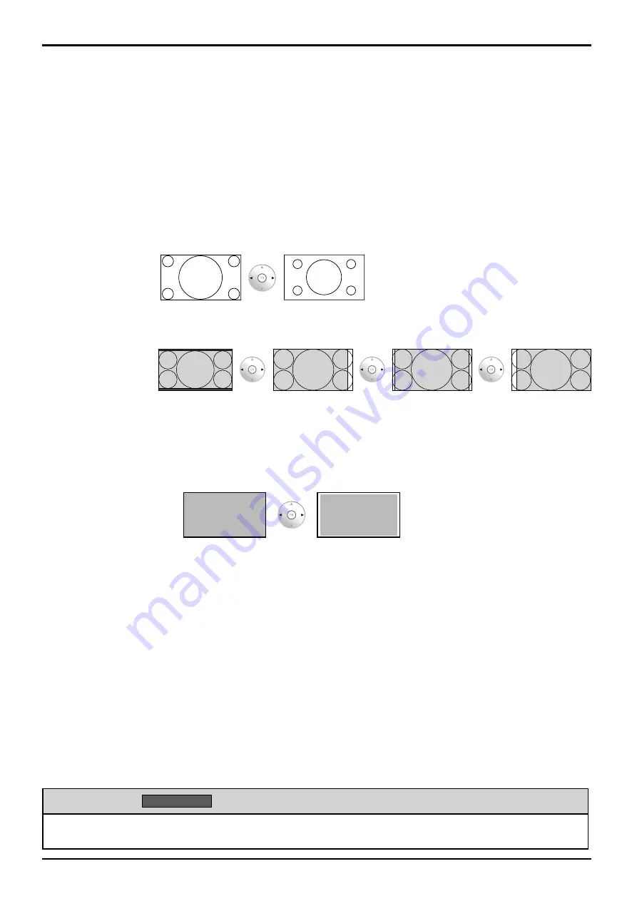
 1:1 Pixel Mode

Adjusts the display size when 1125i, 1125p or 1250i signal is input.

Notes:

Select On when you would like to replay 1920 × 1080 input signal.
Applicable input signal;
1125 (1080) / 50i • 60i • 24sF • 24p • 25p • 30p • 50p • 60p, 1250 (1080) / 50i
Select Off when flickering is shown around the image.
H-Size, V-Size and Dot Clock cannot be adjusted when On is selected.


 Off 

On

  1:1 Pixel Mode 

(2k1k)

  (For 2k1k signals)

When the input signal is a 2k1k signal (2048 × 1080 / 24p, 2048 × 1080 / 24sF), the display 
size is adjusted as follows.


Off 

On (left) 

On (Centre) 

On (Right)

Note:

2k1k signals can only be received when the Dual Link HD-SDI Terminal Board (TY-FB11DHD) 
is installed.

  Display size

Adjusts the image display size on screen.

Off:

  Sets the normal image display size on screen.

On:

  Sets the image display size approximately 95 % of the normal image display.


Off 

On

Notes:

“Display size” can be modified when “Studio mode” in the Options menu is “On”. When 
“Studio mode” is “Off”, this setting is “Off” and cannot be changed. (see page 41)
This setting is valid only when the input signals are as follows;
525i, 525p, 625i, 625p, 750/60p, 750/50p, 1125/60i, 1125/50i, 1125/24sF, 1125/25p, 
1125/24p, 1125/30p, 1125/60p, 1125/50p, 1250/50i (Component Video, RGB, DVI, SDI, 
HDMI)
When “Display size” is set to “On”, “H-Pos” and “V-Pos” in “Pos. /Size” can be adjusted.
Refer to each board’s operating instruction for DVI, SDI, HDMI’s corresponding signals.


Helpful Hint (

Normalise

  Normalization)

While the Pos. /Size display is active, if the OK button is pressed during “Normalise”, then all adjustment values 
are returned to the factory settings.

Содержание TH-50VX100E

Страница 1: ...ions before operating your set and retain them for future reference English The illustration shown is an image Model No TH 50VX100E TH 65VX100E TQBC2382 1 Operating Instructions High Definition Custom Home Theater Plasma Display ...

Страница 2: ...t 32 Screensaver For preventing image retention 33 Reduces screen image retention 34 Side Panel Adjustment 34 Specifying the scaler 35 Reduces power consumption 36 Customizing the On Screen Menu Display 37 Setup for Input Signals 38 Component RGB in select 38 YUV RGB in select 38 Signal menu 39 XGA Mode 39 Sync 40 SDI Through 40 Input signal display 40 Options Adjustments 41 Watching Videos and DV...

Страница 3: ...s noise to appear To avoid the possibility of harm to this appliance keep it away from sources of strong electromagnetic fields IMPORTANT THE MOULDED PLUG IMPORTANT THE MOULDED PLUG FOR YOUR SAFETY PLEASE READ THE FOLLOWING TEXT CAREFULLY This display is supplied with a moulded three pin mains plug for your safety and convenience A 10 amp fuse is fitted in this plug Shall the fuse need to be repla...

Страница 4: ...ort only in upright position Transporting the unit with its display panel facing upright or downward may cause damage to the internal circuitry Ventilation should not be impeded by covering the ventilation openings with items such as newspapers table cloths and curtains For sufficient ventilation If using the pedestal optional accessory leave a space of 10 cm or more at the top left and right and ...

Страница 5: ...ower supply plug with wet hands Doing so may cause electric shocks Do not do anything that may damage the power cable When disconnecting the power cable pull on the plug body not the cable Do not damage the cable make any modifications to it place heavy objects on top of it heat it place it near any hot objects twist it bend it excessively or pull it To do so may cause fire and electric shock If t...

Страница 6: ... from direct or reflected light from your Plasma Display Cleaning and maintenance The front of the display panel has been specially treated Wipe the panel surface gently using only a cleaning cloth or a soft lint free cloth If the surface is particularly dirty wipe with a soft lint free cloth which has been soaked in pure water or water in which neutral detergent has been diluted 100 times and the...

Страница 7: ...rol transmitter Disposal of batteries should be in an environment friendly manner Observe the following precaution 1 Batteries shall always be replaced as a pair Always use new batteries when replacing the old set 2 Do not combine a used battery with a new one 3 Do not mix battery types example Zinc Carbon with Alkaline 4 Do not attempt to charge short circuit disassemble heat or burn used batteri...

Страница 8: ...ation AC cord connection see page 12 Pass the attached cable fixing band through the clip as shown in the figure To secure cables connected to Terminals wrap the cable fixing band around them then pass the pointed end through the locking block as shown in the figure While ensuring there is sufficient slack in cables to minimize stress especially in the power cord firmly bind all cables with the su...

Страница 9: ...onnection Some PC models cannot be connected to the set There is no need to use an adapter for computers with DOS V compatible Mini D sub 15P terminal The computer shown in the illustration is for example purposes only Additional equipment and cables shown are not supplied with this set Do not set the horizontal and vertical scanning frequencies for PC signals which are above or below the specifie...

Страница 10: ...er command 3 bytes Colon Parameter s 1 5 bytes End 03h Notes If multiple commands are transmitted be sure to wait for the response for the first command to come from this unit before sending the next command If an incorrect command is sent by mistake this unit will send an ER401 command back to the computer SL1A SL1B SL2A and SL2B of Command IMS are available only when a dual input terminal board ...

Страница 11: ...ut signal source Digital TV SET TOP BOX DTV STB Connections HDMI connection This unit has terminal boards equivalent to Dual HDMI Terminal Board TY FB10HMD and RCA Component Video Terminal Board TY 42TM6Z as standard equipment HDMI cables DVD Player or SET TOP BOX HDMI compatible machines only Pin assignments and signal names 19 3 1 4 2 18 Note Additional equipment and HDMI cables shown are not su...

Страница 12: ...f Power Indicator Red standby Press the button on the remote control to turn the Plasma Display on Power Indicator Green Turn the power to the Plasma Display off by pressing the switch on the unit when the Plasma Display is on or in standby mode Note During operation of the power management function the power indicator turns orange in the power off state Power Indicator Remote Control Sensor From ...

Страница 13: ...ion is not the perfect solution to image retention Select the input signals to be connected by installing the optional Terminal Boards Initial selections Selecting the On Screen Menu Language Selecting the input signal INPUT Press to select the input signal to be played back from the equipment which has been connected to the Plasma Display HDMI1 HDMI2 HDMI3 HDMI4 COMPONENT PC INPUT HDMI signal ter...

Страница 14: ...ontrol sensor Power Indicator The Power Indicator will light Power OFF Indicator not illuminated The unit will still consume some power as long as the power cord is still inserted into the wall outlet Standby Red Power ON Green DPMS Orange With PC input signal and during operation of PC s screensaver Main Power On Off Switch INPUT button INPUT1 INPUT2 INPUT3 and PC selection see page 13 Enter Aspe...

Страница 15: ...ons PC button Press to select PC input see page 13 OK button Press to make selections COMPO button Press to select COMPONENT or RGB input see page 13 DIRECT INPUT buttons Press the each button to select the INPUT mode see page 13 This button is used to switch directly to INPUT mode VIDEO MENU button Press to select Picture Mode see page 20 Monitor Normal Cinema Dynamic External equipment operation...

Страница 16: ... page 36 Press Yes No Test patterns Test patterns Press to select Yes Press Each time you press a different test pattern is displayed seven in all Colour Bars Red Green Blue Frame 2 lines 2 dots Black 1 window To exit this mode press any button other than EXT SCALER function Each time you press an external scaler is activated or deactivated On External scaler mode Off Use the built in scaler On Us...

Страница 17: ...aspect mode please see List of Aspect Modes page 46 The aspect mode changes each time the ENTER button is pressed 4 3 Zoom 16 9 For PC signal input For SD signal input 525 480 60i 60p 625 575 50i 50p 4 3 Zoom1 16 9 Zoom2 Zoom3 14 9 Just Notes The aspect mode is memorized separately for each input terminal Do not allow the picture to be displayed in 4 3 mode for an extended period as this can cause...

Страница 18: ...Contrast Normalise Brightness Sharpness White balance Colour Management press MENU press several times Each time the MENU button is pressed the menu screen will switch Normal Viewing Picture Setup Pos Size Sound 2 Select the menu 1 select 2 press Setup Pos Size Sound Options Picture Example Sound menu Menus can also be accessed directly by pressing dedicated buttons such as and see page 20 30 3 Se...

Страница 19: ...ory lock Channel 1 Left Channel SDI Sound Output 2 2 Channel 2 Right Channel On Sound Out Off Level Meter see page 20 29 see page 33 40 see page 30 31 see page 32 see page 41 see page 32 see page 39 40 see page 33 34 0 0 0 2 2 Off Off Off Off Input level Advanced settings Normalise Gamma AGC W B High R W B High G 0 W B High B 0 W B Low R 0 W B Low G 0 W B Low B Cinema reality Studio Gain Noise red...

Страница 20: ...ast Dynamic For viewing in brighter environments This menu selects higher than normal levels of Brightness and Contrast Cinema Ideal for movies Monitor For use when creating broadcast or movie content With this picture even if the overall average picture level APL changes the brightness of areas with the same signal level does not change Notes When Monitor is selected in Picture Mode the following...

Страница 21: ... Studio can be modified when Studio mode in the Options menu is On see page 41 Colour Management On Enables colour adjustment automatically Off On Notes Colour and Hue settings cannot be adjusted for RGB PC input signal You can change the level of each function Contrast Brightness Colour Hue Sharpness for each Picture Mode The setting details for normal dynamic and cinema respectively are memorize...

Страница 22: ... light red light green or light blue areas Adjusts the white balance for dark red dark green or dark blue areas Carry out W B adjustment as follows 1 Adjust the white balance of the bright sections using the W B High R W B High G and W B High B settings 2 Adjust the white balance of the dark sections using the W B Low R W B Low G and W B Low B settings 3 Repeat steps 1 and 2 to adjust Steps 1 and ...

Страница 23: ...lows Component Video RGB analog SDI HDMI Noise reduction Sets the following three NR Noise Reduction functions together P NR Mosquito NR Block NR Off Mid Min Advanced Max Advanced NR Sets the three NR functions separately 1 Select Advanced Off Off Advanced P NR Mosquito NR Off Block NR Noise reduction select 2 Select the item and set Off Off Advanced P NR Mosquito NR Off Block NR Noise reduction 2...

Страница 24: ...lour Management On Onscreen display Scrolling bar Off Off All Aspect Studio mode Function button assign Memory lock 25 0 5 6 0 Normal Advanced settings Picture Mode Off Normal Contrast Normalise Brightness Colour Hue Sharpness White balance Colour Management Normal Advanced settings Picture Mode Off Normal Contrast Normalise Brightness Colour Hue Sharpness White balance Colour Management 0 0 0 0 0...

Страница 25: ...e for the profile Entering profile names Profile names can be up to 16 characters To enter text select characters in the on screen keyboard Edit the default profile name in the text box as desired Ok A MEMORY1 Memory name input B C D E F G H I J K L M All delete N O P Q R S T U V W X Y Z Delete Space a b c d e f g h i j k l m n o p q r s t u v w x y z 0 1 2 3 4 5 6 7 8 9 _ ˆ Cancel 1 select 2 OK E...

Страница 26: ...ct 2 OK Loading profiles Load profiles and apply the picture adjustment values to the display as follows Note Loaded profiles are stored in memory according to the selected input terminal SLOT1 2 3 or PC IN Picture Profiles Loading locked profiles In the Picture menu profiles are labeled with these icons to indicate their locked status Picture Mode Dynamic 25 0 Contrast Normalise Brightness Lock1 ...

Страница 27: ... data 1 select 2 OK Renaming profiles Note Locked profiles cannot be renamed 1 In the Picture menu select Memory edit Memory save Memory load Memory edit 2 OK 1 select 2 Select Memory name change Memory name change Memory delete 2 OK 1 select 3 Select the profile to rename 1 MEMORY1 MEMORY2 2 MEMORY12 12 2 OK 1 select 4 Enter a name for the profile Entering profile names page 25 A B C D E F G H I ...

Страница 28: ...profiles 1 Display the menu screen 2 Select Options and hold for 3 seconds or more Setup Pos Size Sound Options Picture 2 OK 3 seconds or more 1 select 3 Select Memory lock On Onscreen display Scrolling bar Off Off All Aspect Studio mode Function button assign Memory lock 2 OK 1 select 4 Enter a 4 digit password The default password is 0123 5 Select OK OK CANCEL Input password 1 select 2 OK 6 Sele...

Страница 29: ...On or Off 4 Exit the menu or Specifying On for isf Mode changes the Picture Mode mode display as follows Picture Mode mode display 25 0 5 6 0 Normal Picture Mode Contrast Normalise Brightness Colour Hue Sharpness isf Mode Off isf Mode On Normal Normal Dynamic isf Mode Day Cinema isf Mode Night Monitor Monitor Mode display when is selected isf Mode Off isf Mode On Picture Mode Cinema Dynamic Normal...

Страница 30: ...sted automatically In such case press Auto Setup again after changing the image to the clearer one When DVI D is input Clock Phase cannot be adjusted automatically Select Normalise in Pos Size and press the OK button when appropriate adjustment cannot be made H Pos Adjust the horizontal position V Pos Adjust the vertical position H Size Adjust the horizontal size V Size Adjust the vertical size 1 ...

Страница 31: ...left On Centre On Right Note 2k1k signals can only be received when the Dual Link HD SDI Terminal Board TY FB11DHD is installed Display size Adjusts the image display size on screen Off Sets the normal image display size on screen On Sets the image display size approximately 95 of the normal image display Off On Notes Display size can be modified when Studio mode in the Options menu is On When Stu...

Страница 32: ...ts right audio channel Sound Out On Off On Enables audio output Off Disables audio output Level Meter Off 1 8ch 9 16ch Sets audio channels to show in the audio level meter 8 channels are displayed in the audio level meter 4 channels each on both right and left sides of the display Off Hides the audio level meter 1 8ch Displays the audio level meter 1 8ch 9 16ch Displays the audio level meter 9 16c...

Страница 33: ... Negative image White screen Negative image Negative image will be displayed on the screen Scrolling bar only A white bar will scroll from left to right The image won t be displayed Overlay scrolling bar The brightness of the image will be decreased and a white bar will scroll on it White screen The whole screen will be white 5 Start setting Select Start Side panel Screensaver Start Wobbling Peak ...

Страница 34: ...e On1 Shifts the image every 30 seconds On2 Shifts the image at a dot level pitch depending on screen detection Peak limit Suppresses image contrast peak brightness Note When a still picture is viewed for an extended time the screen may become slightly darker see page 45 1 Select Wobbling or Peak limit 2 Select On1 On2 or Off Wobbling Select On or Off Peak limit Negative image Off Off High Side pa...

Страница 35: ...xternal scaler Note Selecting On in this setting deactivates the following settings and disables these operations Pos Size menu H Size V Size 1 1 Pixel Mode Display size see page 30 31 Picture menu Brightness Colour Hue Sharpness Memory save Memory load see page 21 25 26 Advanced settings Cinema reality Noise reduction see page 23 Signal menu XGA Mode see page 39 Options menu All Aspect see page 4...

Страница 36: ... of the microcomputer is reduced during power supply standby see page 12 14 15 so standby power of the set is reduced Power management When this function is set to On it operates under the following conditions to turn the power on or off automatically When no pictures HD VD sync signals are detected for 30 or so seconds during PC IN signal input Power is turned off standby the power indicator ligh...

Страница 37: ...ype1 Type2 Type3 4 Specify the display position Select OSD position and choose the display position Standby save Power management Auto power off Off Off On OSD design Type1 OSD position Upper left OSD Language English UK 2 change 1 select Each time you press or the on screen menu display position changes Display example Upper left Centre 5 Exit the menu or Component RGB in select External scaler m...

Страница 38: ... depending on which optional board is installed Make setting of the selected input terminal SLOT1 SLOT2 SLOT3 or PC IN YUV RGB in select Select to match the signals from the source connected to the DVI input terminals YUV signals YUV RGB signals RGB 1 Display the menu screen 2 Select Setup Setup Pos Size Sound Picture 2 OK 1 select 3 Select YUV RGB in select and set YUV RGB in select External scal...

Страница 39: ...mponent H Freq V Freq Signal Format Digital 33 7 kHz 60 0 Hz 1125 1080 60i 108 0 MHz Dot Clock Freq Signal H Freq V Freq Signal Format XGA Mode This menu is displayed when the input signal is analog Component PC This unit supports three types of XGA signals with 60Hz vertical frequency having different aspect ratios and sampling rates 1 024 768 60Hz 1 280 768 60Hz and 1 366 768 60Hz Be sure to mak...

Страница 40: ...l which is input from the G connector VBS Uses a synchronized signal of Composite Sync input which is input from the HD connector SDI Through Set the active through function of the Dual Link HD SDI Terminal Board TY FB11DHD Note Settings can only be performed for this menu when a slot mounted with a Dual Link HD SDI Terminal Board TY FB11DHD is selected Signal Digital Off SDI Through 2 change 1 se...

Страница 41: ...itched On and Off Cannot be specified set to Off and cannot be changed Display size Can be switched On and Off Cannot be specified set to Off and cannot be changed Function button assign Specifies the function activated when the button on the remote control is pressed Scrolling bar Activates the Scrolling bar only screensaver After 15 minutes the display enters standby mode Test patterns Each time...

Страница 42: ... see page 43 1 Select the input mode see page 13 HDMI1 HDMI2 HDMI3 HDMI4 COMPONENT PC INPUT INPUT 2 Select the remote control mode Press the key to select DISPLAY VCR DBS CBL DVD 3 Operate the connected equipment pointing Display s remote control at the equipment Example VCR MODE DVD MODE VCR Record Record Skip Reverse Forward Rewind Fast Forward Reverse Forward Stop Stop Pause Pause Play Play For...

Страница 43: ...AY If the equipment does not operate with the remote control When your equipment has a single code Input the remote control code again When your equipment has multiple codes Change the code with 4 above and test again Note Registration will fail if the wrong code is input or it takes more than 30 seconds to register To find a code not listed in the code list This procedure searches all codes and i...

Страница 44: ...ent RGB in select RGB External scaler mode Power save Standby save Power management Auto power off Off Off On Off Off OSD design Type1 OSD position Upper left OSD Language English UK Screensaver Signal 1 select 4 Press for more than 5 seconds 5 Select YES YES NO Reset to factory default 1 select 2 OK 6 Select YES and wait for 10 sec YES NO All saved data will be erased CONTINUE 1 select 2 OK Execu...

Страница 45: ...ence a slight time lag may occur between image and audio depending on the type of input signal However this is not a malfunction Plasma Display panel Symptoms Check The screen darkens slightly when bright pictures with minimal movements are shown The screen will darken slightly when photos still images of a computer or other pictures with minimal movements are shown for an extended period This is ...

Страница 46: ...e screen is slightly elongated 4 3 4 3 Pictures with a 4 3 aspect ratio are displayed with their original aspect ratio Side panels are displayed at the left and right edges of the screen 4 3 1 4 3 2 The pictures with a 4 3 aspect ratio among the 16 9 aspect ratio signals are displayed with their original aspect ratio The left and right edges of the pictures are masked with side panels 4 3 Full 4 3...

Страница 47: ...morex 0000 Motorola 0276 0476 0810 1106 1187 1254 1376 Multitech 0883 Myrio 1602 1822 Pace 0008 0237 1877 Panasonic 0000 0107 1786 Panther 0637 Paragon 0000 Philips 0317 1305 Pioneer 0144 0533 0877 1877 Pulsar 0000 Quasar 0000 RadioShack 0883 RCA 1256 Regal 0273 0279 Runco 0000 Samsung 0144 Scientific Atlanta 0008 0017 0477 0877 1877 Sejin 1602 Sony 1006 Starcom 0003 Supercable 0276 Supermax 0883 ...

Страница 48: ...g 0037 0047 0072 0240 Curtis Mathes 0035 0041 0060 0162 1035 Cybernex 0240 CyberPower 1972 Daewoo 0045 0278 1278 Dell 1972 Denon 0042 DirecTV 0739 0740 0745 1239 1240 Durabrand 0038 0039 Dynatech 0000 Electrohome 0037 Electrophonic 0037 Emerex 0032 Emerson 0000 0002 0037 0043 0121 0184 0209 0278 0479 0593 1278 1479 1593 Fisher 0047 0104 Fuji 0033 0035 Funai 0000 0593 1593 Garrard 0000 Gateway 1972...

Страница 49: ...768 70 Hz 56 48 70 07 75 0 33 1 024 768 75 Hz 60 02 75 03 78 75 34 1 024 768 85 Hz 68 68 85 00 94 5 35 1 066 600 60 Hz 37 64 59 94 53 0 53 0 36 1 152 864 60 Hz 53 70 60 00 81 62 37 1 152 864 75 Hz 67 50 75 00 108 0 38 1 280 768 60 Hz 47 70 60 00 80 14 39 1 280 960 60 Hz 60 00 60 00 108 0 40 1 280 960 85 Hz 85 94 85 00 148 5 41 1 280 1 024 60 Hz 63 98 60 02 108 0 108 0 42 1 280 1 024 75 Hz 79 98 75...

Страница 50: ...27 00 720 858 480 525 3 625 50p 50 00 31 25 27 00 720 864 576 625 4 750 60p 60 00 45 00 74 25 1280 1650 720 750 5 750 50p 50 00 37 50 74 25 1280 1980 720 750 6 1125 60i 60 00 33 75 74 25 1920 2200 1080 1125 7 1125 50i 50 00 28 13 74 25 1920 2640 1080 1125 8 1125 60p 60 00 67 50 148 50 1920 2200 1080 1125 9 1125 50p 50 00 56 26 148 50 1920 2640 1080 1125 10 1125 24p 24 00 27 00 74 25 1920 2750 1080...

Страница 51: ...erminals HDMI A B TYPE A Connector 4 COMPONENT RGB IN Y G RCA PIN JACK PB B PR R RCA PIN JACK AUDIO IN RCA PIN JACK 2 with sync 1 0 Vp p 75 Ω 0 7 Vp p 75 Ω 0 5 Vrms PC IN HIGH DENSITY MINI D SUB 15PIN B PB CB R PR CR HD VD VBS use HD port AUDIO IN M3 JACK Y or G with sync 1 0 Vp p 75 Ω Y or G without sync 0 7 Vp p 75 Ω 0 7 Vp p 75 Ω 0 7 Vp p 75 Ω 1 0 5 0 Vp p high impedance with picture 1 0 Vp p h...

Страница 52: ...ers in the European Union If you wish to discard electrical and electronic equipment please contact your dealer or supplier for further information Information on Disposal in other Countries outside the European Union These symbols are only valid in the European Union If you wish to discard these items please contact your local authorities or dealer and ask for the correct method of disposal Note ...

Отзывы: