VFG
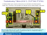
(screw)
VF5V
SRV VF5V
SRV VF5V
VFO
SRV VFO
SRV VFO
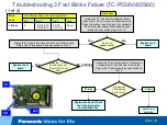
Troubleshooting 7 Blinks Failure (VFO/VF5V Resistance Check)
From the previous page
Using any of the VFG screws (Floating ground screws) on the SU or
SD board as ground, measure the resistance of both test points:
VF5V (SRV – VF5V) and VFO (SRV – VFO) on the SU board.
(See the picture below.)
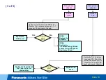
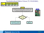
Yes
No
Is there a
short
circuit?
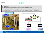
See the picture “A” on the next slide
and:
• Remove the 2 or 4 VFG screws
from the SU and SD boards.
• Unplug SC41, SC42, and SC46
from the SC board.
• Install the SC50 Jig or just jump
pins 1 and 2 of connector SC50 on
the SC board.
• Plug in the TV and turn it on.
A - Continue
on the next
slide
Yes
No
Does the TV
shut down
with 7 blinks?
Replace both
the SU and
SD boards
Replace the SC
board.
(2 of 4)
Slide 24
VFO
VF5V
VFG
SC
SC
SU
SU
SD
SD
SC41
SU41
SC42
SD42
Содержание TC-P2013TI
Страница 35: ...Video Lines Troubleshooting Slide 35 ...
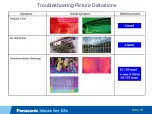
Страница 36: ...Troubleshooting Picture Distortions Slide 36 ...
Страница 37: ...Troubleshooting Picture Distortions Slide 37 ...
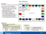
Страница 39: ...Test Patterns Slide 39 ...
Страница 40: ...Defective Panel Drive IC Slide 40 ...

