


22
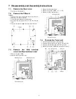
3. Remove the Rear cover hooks (L, R).
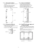
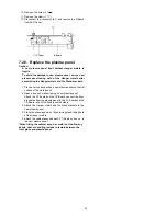
7.18. Remove the S-Board
1. Remove the Cabinet assy. (See section 7.17.)
2. Remove the S-Board shield case.
3. Remove the screws (
×
2
) and remove the S-Board
unit.
4. Disconnect the connector (S2).
5. Remove the Power button.
6. Remove the screw (
×
1
) and remove the S-Board.
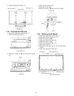
7.19. Remove the K-Board
1. Remove the Cabinet assy. (See section 7.17.)
2. Remove the S-Board. (See section 7.18.)
3. Remove the screws (
×
5 ).
4. Remove the Glass holder bottom rear.
5. Remove the screws (
×
4 ).
6. Remove the Glass holder side (L, R).
7. Remove the screws (
×
7 ).
8. Remove the Glass holder top rear and the Glass holder
top front.
9. Remove the Glass holder bottom front.
Содержание TC-42PX14 - 42" Plasma Panel
Страница 15: ...15 6 4 No Picture ...
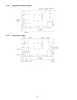
Страница 26: ...26 8 1 4 Adjustment Volume Location 8 1 5 Test Point Location ...
Страница 28: ...28 ...
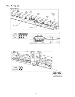
Страница 34: ...34 10 3 Wiring 2 ...
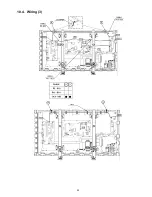
Страница 35: ...35 10 4 Wiring 3 ...
Страница 36: ...36 10 5 Wiring 4 ...
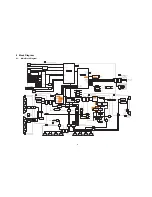
Страница 37: ...37 11 Schematic Diagram 11 1 Schematic Diagram Note ...
Страница 66: ...66 12 Printed Circuit Board 12 1 P Board A B C D E F G H I 1 2 3 4 5 6 P BOARD FOIL SIDE LSEP1279ANHB ...
Страница 68: ...68 A B C D E F G H I 1 2 3 4 5 6 P BOARD COMPONENT SIDE LSEP1279ANHB ...
Страница 80: ...80 ...
Страница 82: ...82 13 1 2 Accessories ...
Страница 83: ...83 13 1 3 Mechanical Replacement Parts List ...
Страница 86: ...86 13 2 Electrical Replacement Parts List 13 2 1 Replacement Parts List Notes ...


