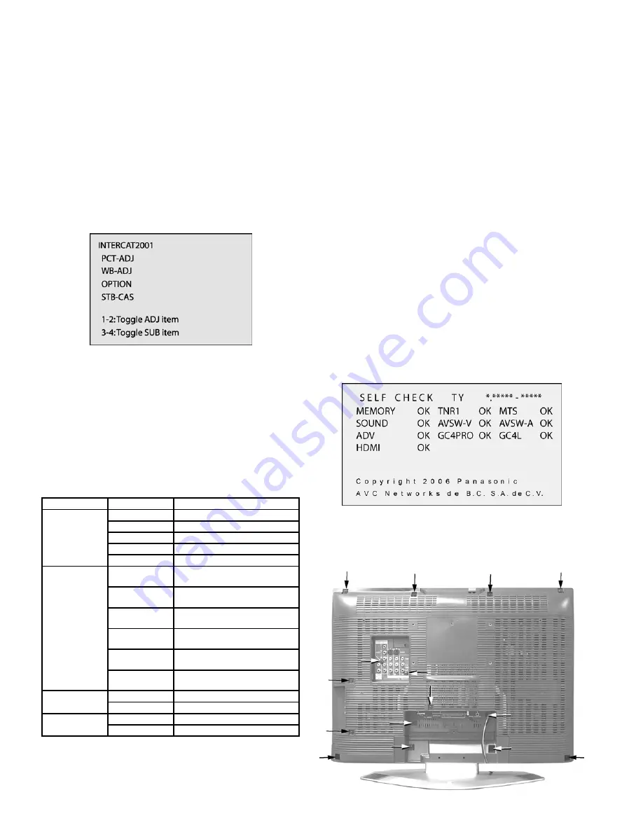
7 Service Mode
7.1. How to enter into adjustment
mode
While pressing [VOLUME-] button of the main unit, press
[RECALL] button of the remote control transmitter three times
in a row (within 2 seconds).
7.2. Adjustment method.....Use the
remote control.
“1” button...Main items Selection in forward direction
“2” button...Main items Selection in reverse direction
“3” button...Sub items Selection in forward direction
“4” button...Sub items Selection in reverse direction
7.3. Cancellation
Switch off the power with the [POWER] button on the main unit
or the [POWER] button on the remote control.
7.4. Contents of adjustment mode
•
Value is shown as a hexadecimal number.
•
Preset value differs depending on models.
•
After entering the adjustment mode, take note of the value
in each item before starting adjustment.
Main Item
Sub Item
Remarks
PCT-ADJ
COLOR
Sub color
R-Y-A
R-Y recovery axis (R-Y)
R-Y-G
B-Y Gain (B-Y)
BACK-L
Sub backlight
TINT
Tint Adjustment
WB-ADT
B-CENT
Adjustment of Blue gain by test
pattern (50% white)
G-CENT
Adjustment of Green gain by test
pattern (50% white)
R-CENT
Adjustment of Red gain by test
pattern (50% white)
B-GAIN
Adjustment of Blue gain by test
pattern (100% white)
G-GAIN
Adjustment of Green gain by test
pattern (100% white)
R-GAIN
Adjustment of Red gain by test
pattern (100% white)
OPTION
OPTDD
White 100% (Not ADJ)
BOOT
Red 100% (Not ADJ)
STB-CAS
8 Troubleshooting Guide
8.1. Self-check function
When phenomena like "the power fails from time to time" or
"the video/audio fails from time to time" can not be
confirmed at the time of servicing, the self-check function
can be used to confirm the occurrence and to limit the
scope for the defective circuits. Also, when "the power fails
from time to time", display on the screen can be used to
confirm the occurrence and to limit the scope for the
defective circuits.
Any programmed channels, channels caption data and
some other user defined settings will be erased and return
to factory setting.
8.2. How to access
Access
Produce TV reception screen and, while pressing
[VOLUME -] button on the main unit, press [SLEEP] button
on the remote controller unit simultaneously.
Exit
Press the POWER button twice (off/on) to return to the
normal screen.
8.3. Screen Display
9 Disassembly Instructions
Back cover removal (screw location)
8
Содержание TC-26LX600 - 26" LCD TV
Страница 7: ...6 Location of controls EUR7613ZF0 7 ...
Страница 14: ...11 Boards Assemblies 11 1 AP Board 14 ...
Страница 15: ...11 2 A Board 15 ...
Страница 16: ...11 3 P Board 16 ...
Страница 17: ...11 4 G Board 17 ...
Страница 18: ...11 5 DT Board 18 ...
Страница 19: ...11 6 DT Board with shield 19 ...
Страница 20: ...11 7 V Board 20 ...
Страница 31: ...13 Schematic Diagrams 13 1 Schematic Diagrams Notes 31 ...
Страница 32: ...13 2 Reference of PDF links color 32 ...
Страница 37: ...13 7 V Board Schematic Diagram 1 2 3 4 5 6 7 8 A B C D E F G H I J V BOARD TNPA3789 TC 26LX600 TC 32LX600 37 ...
Страница 38: ...13 8 G Board Schematic Diagram 38 ...
Страница 39: ...1 2 3 4 5 6 7 8 A B C D E F G H I J G BOARD TNPA3784 TC 26LX600 TC 32LX600 39 ...
Страница 42: ...14 3 AP Board 0 1 2 J I F 7777777 EJ L 777777 I IK77777 A BBC7 A BB 42 ...
Страница 43: ...14 4 DT Board Bottom Side 0 1 2 34 5 6 7777777389 4 777777 5335 777773 4 73 4 43 ...
Страница 44: ...14 5 DT Board Top Side 0 1 2 34 5 6 7777777389 4 777777359777773 4 73 4 44 ...
Страница 46: ...15 Parts Location LCD TV Exploded View 15 1 Packing Exploded View Package contents 46 ...
Страница 47: ...16 Parts list 16 1 Description of abbreviations guide 47 ...
Страница 65: ...1 5 AP BOARD FOIL SIDE A B C D E F G H I 1 2 3 4 5 6 AP BOARD FOIL SIDE 7 ...
Страница 66: ...1 6 AP BOARD COMPONENT SIDE A B C D E F G H I 1 2 3 4 5 6 AP BOARD COMPONENT SIDE 8 ...


