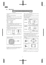
background image

Colour Purity

 1. Set the Brightness and Contrast controls to their maximum

positions.

 2. Operate the TV set for 60 minutes.
 3. Fully degausse the picture tube by using an external

degaussing coil.

 4. Apply a crosshatch pattern signal and adjust the static

convergence magnets to the approximately correct position.

 5. Receive a black and white signal.
 6. Set the control as follows:

Red................minimum
Green.............minimum
Blue...............minimum
Press the Shipping button on the remote control twice to
select CRT Adjustment Mode to select low light.

 7. Loosen the clamp screw for the Deflection Yoke A in Fig. 10

and move the Deflection Yoke as close to the purity magnet
as possible.

 8. Adjust the purity magnetic rings so that a vertical green field

is obtained at the centre of the screen.

Fig. 6

 9. Slowly push the Deflection Yoke and set it where a uniform

green field is obtained.

Fig. 21

 10. Re-adjust the Low Light controls to their correct settings

and make sure that a uniform white field is obtained.

 11. Tighten the clamp screw A in Fig. 10.

Convergence

 1. Apply a crosshatch pattern signal and Normalize Contrast

control to the maximum positions.

 2. Adjust Brightness until the grey position of the crosshatch

pattern just becomes black.

 3. Adjust the Red and Blue line at the centre of the screen by

rotating the R-B static.

Fig. 8

 4. Adjust Red and Blue with Green line at centre of the screen

by rotating (RB)-G static convergence magnetic rings.

 5. Lock convergence magnets with silicone sealer.
 6. Remove the DY wedges and slightly tilt the Deflection Yoke

vertically and horizontally to obtain the good overall
convergence.

Fig. 9

 7. Fix the Deflection Yoke by reinserting the DY wedges. Refer

to Fig. 10.

 8. If purity error is found, repeat “Colour Purity” adjustment.

2.6. Adjustment

Before Colour Purity, Convergence and White Balance adjustment are attempted,

V. Height, H. Centre and Focus adjustments must be completed.

10

TC-21GX20P

Содержание TC-21GX20P

Страница 1: ...007 Matsushita Electric Industrial Co Ltd All rights reserved Unauthorized copying and distribution is a violation of law TC 21GX20P GL1 Chassis Video Out 1 Vp p 75 Audio Out Approx 0 5V 1k High Volta...

Страница 2: ...vice Hints 5 2 1 Service Position for E Board 5 2 2 Factory Mode Adjustment 5 2 3 Adjustment for White Balance 8 2 4 Adjustment for CRT CUT OFF 8 2 5 Adjustment Procedure 9 2 6 Adjustment 10 3 Conduct...

Страница 3: ...sed metallic cabinet part on the receiver such as screw heads aerials connectors control shafts etc When the exposed metallic part has a return path to the chassis the reading should be between 4 M an...

Страница 4: ...AW Rear Inputs AV1 V L R Front Inputs AV2 V L R YUV YUV CVBS4 CVBS2 IF V H V OUT H OUT R G B R G B CRT defl coil MONITOR OUT SDA SCL Audio Out Mon Out AUDIO AMP IC2302 IC601 UOC EEPROM IC1103 IC851 5V...

Страница 5: ...nt a Set Timer ON 30 minutes Press remote s RECALL panel s vol down key simultaneously to select service mode b CHK should appear on right side of TV screen After few seconds CHK 1 should appear on ri...

Страница 6: ...ion will be as follows f Press digit key 4 to move forward from Colour Sub Colour etc Press digit key 3 to move backward from Sub Colour Colour etc g Press volume up volume down to adjust setting h Pr...

Страница 7: ...e backward from G CUT R CUT n After selecting the required mode press volume up volume down to adjust required setting o Press digit key 5 to make the AKB OFF and H Line mode first time Press digit ke...

Страница 8: ...FF so that X 0 233 0 015 nit 3 Adjustment G CUT OFF so that Y 0 235 0 015 nit Adjustment of High Light 1 Adjustment Sub Bright so that Y 150 nit 2 Adjustment R Drive so that X 0 262 0 010 nit 3 Adjust...

Страница 9: ...follows TPA 10 141 1 5V TPA 12 3 3 0 5V TPA 09 5 1V 2 5 2 High Voltage Item preparation 1 Receive the crosshatch pattern 2 Set to 0 Beam Screen VR minimum Contrast minimum Adjustment procedure 1 Conn...

Страница 10: ...ined Fig 21 10 Re adjust the Low Light controls to their correct settings and make sure that a uniform white field is obtained 11 Tighten the clamp screw A in Fig 10 Convergence 1 Apply a crosshatch p...

Страница 11: ...primarily Fig 1 Purity magnet Set purity magnet that 2 magnets are TOP POSITION VRS magnet Set purity magnet 2 magnets are HORIZONTAL POSITION 2 Adjustment a Receive that Cross Hatch pattern b Adjust...

Страница 12: ...and 3 shown in Fig 11 2 The wedges should be set 120 apart from each other 3 Be certain that three wedges are firmly fixed and the Deflection Yoke is tightly clamped in place Otherwise the Deflection...

Страница 13: ...3 Conductor Views 13 TC 21GX20P...

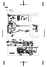
Страница 14: ...4 Schematic Diagram 14 TC 21GX20P...

Страница 15: ...15 TC 21GX20P...

Страница 16: ...4 1 A Board 4 1 1 A Board 1 5 1A 2A 3A 5A 4A 6A 7A 8A 9A 16 TC 21GX20P...

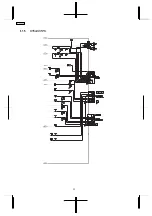
Страница 17: ...4 1 2 A Board 2 5 1B 2B 4B 3B 7B 6B 5B 8B 9B 1A 2A 3A 5A 4A 6A 7A 8A 9A 17 TC 21GX20P...

Страница 18: ...4 1 3 A Board 3 5 1C 2C 4C 3C 7C 6C 5C 8C 9C 1B 2B 4B 3B 7B 6B 5B 8B 9B 18 TC 21GX20P...

Страница 19: ...4 1 4 A Board 4 5 1D 2D 7D 4D 3D 8D 6D 5D 9D 1C 2C 4C 3C 7C 6C 5C 8C 9C 19 TC 21GX20P...

Страница 20: ...4 1 5 A Board 5 5 1D 2D 7D 4D 3D 8D 6D 5D 9D 20 TC 21GX20P...

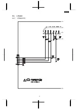
Страница 21: ...4 2 L Board 4 2 1 L Board 1 3 1A 2A 3A 4A 5A 21 TC 21GX20P...

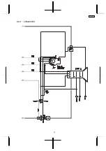
Страница 22: ...4 2 2 L Board 2 3 1B 2B 3B 4B 5B 6B 1A 2A 3A 4A 5A 22 TC 21GX20P...

Страница 23: ...4 2 3 L Board 3 3 1B 2B 3B 4B 5B 6B 23 TC 21GX20P...

Страница 24: ...5 Parts Locations 24 TC 21GX20P...

Страница 25: ...6 Replacement Parts List 25 TC 21GX20P...

Страница 26: ...me Description Remarks C515 F1B2H331A025 C 330PF 500V C516 F2A1E102A199 E 1000UF 25V C519 F2A2C330A096 E 33UF 160V C520 F2A0J221A317 E 220UF 6 3V C550 ECQM4223JZ P 0 022UF J 400V C552 F2A2E1000023 E 1...

Страница 27: ...1101 TALV35VB331K PEAKING COIL L2140 J0JKA0000038 BEAD CORE L3137 J0JKA0000024 EMI FILTER L350 J0JKA0000038 BEAD CORE L501 G0D820000005 LINEARITY COIL L550 J0JKB0000038 COIL L600 G0C100K00008 COIL L60...

Страница 28: ...ER050CKF9532 M95 3KOHM F 1 2W R558 ERDS2TJ513 C 51KOHM J 1 4W R559 D0C12R7JA042 M 2 7OHM J 1W R560 ERG1SJ102E M 1KOHM J 1W R563 ERJ3GEY0R00 M 0OHM J 1 16W Ref No Part No Part Name Description Remarks...

Страница 29: ...0OHM J 1 16W JSA123 ERJ3GEY0R00 M 0OHM J 1 16W JSA124 ERJ3GEY0R00 M 0OHM J 1 16W JSA3000 ERJ3GEY0R00 M 0OHM J 1 16W JSA3001 ERJ3GEY0R00 M 0OHM J 1 16W JSA3132 ERJ3GEY0R00 M 0OHM J 1 16W JSA3133 ERJ3G...

Отзывы: