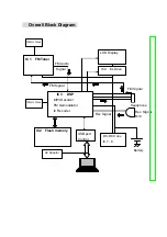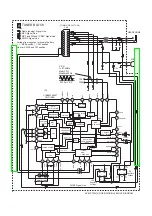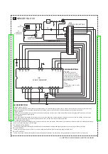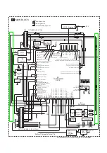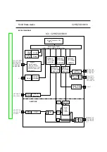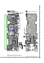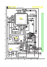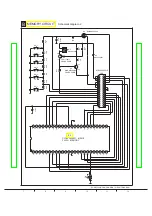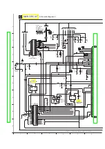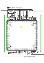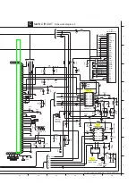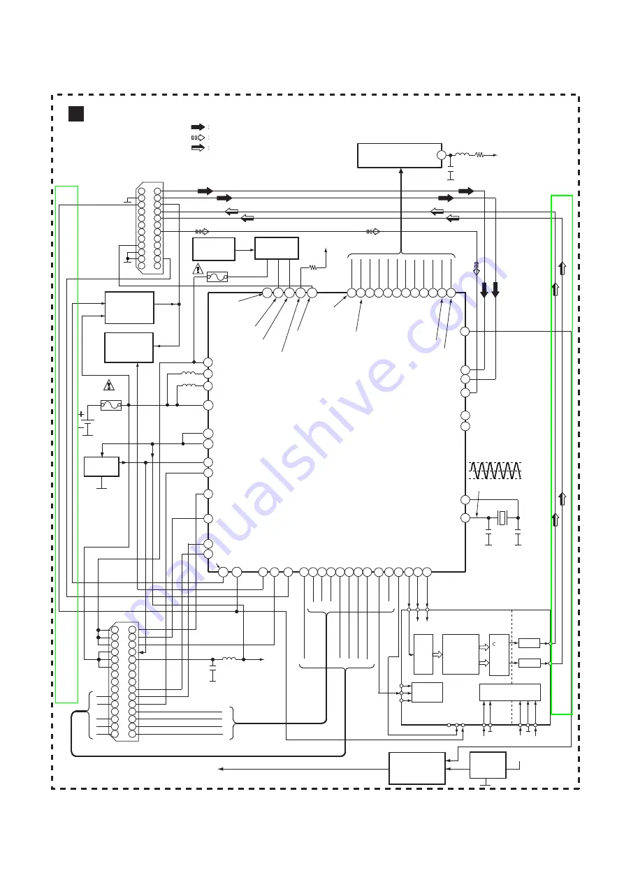
SV-MP720V(GC/GK/GH/GD/GN) BLOCK DIAGRAM
MAIN BLOCK
C
M17
R18
M16
V10
A17
C9
E18
D16 MPMC address 3
MPMC
address 16
MPMC data input/output 0
MPMC data input/output 4
MPMC data input/output 3
MPMC data input/output 2
MPMC data input/output 1
MPMC data input/output 5
MPMC data input/output 7
MPMC data input/output 6
DAI Serial data input
MPMC_NOE:
Output enable for static memories.
Active LOW. Used for static
memory devices.
MPMC_NSTCS_0:
Static memory chip select 0.
Default active LOW. Used
for static memory device.
U17
U14 T17
T15
B14
A13
A14
A1 A2
A3
B2
A4 B4 A5 B5
DAO Bitclock
DAO Serial data out
DAO W
ordselect
G18 F18 F17
G16
IC3
C2HBZG000008
O
P
Q
R
S
U
V
W
DSP IC
15
14
5
7
9
11
13
12
10
8
6
3
4
1
2
17
16
19
18
21
20
23
22
24
CN2
20
2
1
3
4
5
6
7
8
9
10
11
12
13
14
15
16
17
18
19
24
21
22
23
CN1
25
26
27
28
29
30
O
P
Q
R
S
T
U
V
W
T
A12 MPMC_BLOUT0:
The signals nMPMCBLSOUT[0]
select byte lane [7:0] on the data bus.
Used for static memories.
3.3V
LCD1 Display
XATLL_OUT
XTALH_IN
HP_OUTCA: HEADPHONE common output reference
HP_OUTCB: HEADPHONE common output reference
ADC_VINR: SADC Right Analog Input
ADC_VINL: SADC Left Analog Input
LCD_RW-WR:
6800 read/write select 8080 active "high" write enable
LCD_E_RD: 6800 enable
8080 active "high" write enable
LCD_DB_4
LCD_DB_5
LCD_DB-7
LCD_DB_6
LCD_DB_1
LCD_DB-3
LCD_DB_2
LCD_RS: 'high' Data
register selsct 'low'
Instruction register select
LCD_DB-0
LCD_CSB: Chip Select
T1
T4
N1
N2
T10
V9
F3
C2
B3
C1 C3 D2 D1 D3 E2 E3 F2 G2
R3
X2
12MHz
15
3.3V
VDD
IC7
DC-DC
CONV
IC4
EL
DRIVER
D18
ADC_MIC: Microphone Input
BATTERY
1.2V
J17
USB_DP: Positive USB data line
usb 2.0 FS
USB_DM:
Negative USB data line
usb 2.0 FS
USB_RPU: Soft connect output usb 2.0 FS
USB_VBUS:
USB Supply detection line
usb 2.0 FS & usb 2.0
USB PORT
CN3
3.3V
(TO TUNER CIRCUIT CN6)
(TO MEMORY CIRCUIT CN5)
ICP1
REC Signal Line.
Radio Signal Line.
Notes :
MP3/FM/IC REC Signal Line.
N17
T18
P17
L10
L7
ADAPTOR
IN VCC 5V
DC_DC_LX2:
Connection to DC/DC2 external coil
DC_DC_LX1:
Connection to DC/DC1 external coil
DC_DC_VBAT:
Battery supply voltage
MPMC address 2
MPMC
address 15
MPMC address 5
D18
MPMC address 4
12 MHz clock input
12 MHz clock input
3V
3.26V
3.26V
0V
430.0mV P-P
ICP2
1.2V
DC_DC_VUSB:USB supply voltage
MPMC
address 18
IC9
Battery 1.2V
Battery Chargeable Control Pin
Reset
Chargeable
Control
Q7
Battery
IC10
Regulator
DC/DC1 3.3V output voltage
DC/DC1 3.3V input voltage
Analog supply 10-bit ADC
L35
MPMC data input/output 7
C6
Clear to send
(active low)
K2
256 fs clock input
F16
BCK
LRCK
DIN
SERIAL
INTER-
FACE
DIGITAL
8FS FLUENCY
INTERPOLATOR
with
FUNCTION
CONTROLLER
&
PWM
MODU-
LATOR
ANALOG
DRIVER
DRIVER
OUTL
OUTR
FUNCTION
CONTROL
INTERFACE
MC
MD
ML
PDB
SCK
RSTB
DVDD
DGND
POWER SUPPLY
+3.3V
+3.3V +3.3V
A
VDDL
AGND
A
VDDR
IC3
D-SOUND
Serial datd IIC Slave
Содержание SV-MP720VGC
Страница 12: ...8 2 Checking Procedures for Font table 12 PDF created with pdfFactory Pro trial version www pdffactory com ...
Страница 14: ...14 PDF created with pdfFactory Pro trial version www pdffactory com ...
Страница 15: ...15 PDF created with pdfFactory Pro trial version www pdffactory com ...
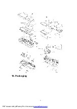
Страница 21: ...18 Packaging 21 PDF created with pdfFactory Pro trial version www pdffactory com ...

