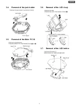
3.5.
Removal of the Main P.C.B.
5
3.6.
Removal of the LCD Ass
馳
5
3.7.
Removal of the LCD holder
5
3.8.
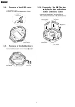
Removal of the USB cover
6
3.9.
Removal of the holder knob
6
3.10. Removal of the REC button and play button and volume
button and mode button
6
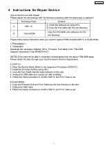
4 Instructions for Repair Service
7
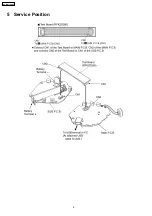
5 Service Position
8
6 Service Mode
9
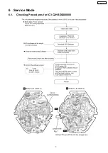
6.1.
Checking Procedures for IC3 C2HBZG000008
9
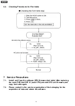
6.2.
Checking Procedures for Font table
10
7 Service Precautions
10
·
Stereo earphones
(L0BAB0000193) .................... .................... .................... . 1pc.
·
USB Cable
(K1HA05AD0004)............. .................... .................... ........ 1pc.
7.1.
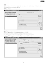
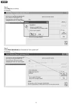
Install and Copy the software (DFU,firmware,font table)
After replacing the main PCB and DSP IC (main
CPU),reinstall DFU and firmware,and copy font table
again.
10
7.2.
Please contact to the service organization of the belonging
for the acquisition of data and obtain the software.
10
8 Troubleshooting
14
9 Troubleshooting guide
14
10 Type Illustration of ICs, Transistors and Diodes
15
11 Block Diagram
16
12 Schematic Diagram Notes
21
13 Schematic Diagram
22
14 Printed Circuit Board Diagram
26
15 Cabinet Parts Location
28
16 Packaging
29
17 Replacement Parts List
29
·
Neck Strap
(VFC4028) .................... .................... .................... .........1pc.
·
CD-ROM Driver
(RFET0002) .................... .................... .................... ........ 1pc.
1 Accessories
2
SV-MP100VGC
Содержание SV-MP100VGC
Страница 7: ...4 Instructions for Repair Service 7 SV MP100VGC ...
Страница 8: ...5 Service Position 8 SV MP100VGC ...
Страница 9: ...6 Service Mode 6 1 Checking Procedures for IC3 C2HBZG000008 9 SV MP100VGC ...
Страница 11: ...11 SV MP100VGC ...
Страница 12: ...12 SV MP100VGC ...
Страница 13: ...13 SV MP100VGC ...
Страница 28: ...15 Cabinet Parts Location 28 SV MP100VGC ...

