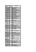
Pin
No.
Mark
I/O /
Division
Function
1
PDE
I
Tracking signal input (1)
terminal
2
I
Tracking signal input (2)
terminal
3
V
DD
I
Power supply input terminal
4
PDA
I
Focus signal input (1)
terminal
5
PDB
I
Focus signal input (2)
terminal
6
LPD
I
APC amplifier input terminal
7
LD
O
APC amplifier output terminal
8
RF
O
RF addition output terminal
9
RF IN
I
RF detection signal input
terminal
10
CSBRT
I
Capacitor connection
terminal for OFTR
11
CEA
I
HPF amplifier capacitor
connection input terminal
12
BDO
O
Dropout signal output
terminal / (H: dropout)
13
LDON
I
APC control input terminal
14
GND
—
Connected to GND
15
/RFDET
O
RF detection signal output
terminal / (L: detection)
16 PDOWN
O
Reduced voltage detection
signal output terminal
17
OFTR
O
Off-track signal output
terminal / (H: off-track)
18
NC
—
Not used, open
19
ENV
O
RF envelop signal output
terminal
20
ENV
OFF
I
Envelop control input
terminal
21
NC
—
Not used, open
22
TE IN
I
Tracking error amplifier
input terminal
23
TE OUT
O
Tracking error amplifier
output terminal
24
FE OUT
O
Focus error amplifier output
terminal
25
FE IN
I
Focus error amplifier input
terminal
26
VREF
O
Reference voltage output
terminal
33
Содержание SL-VP48
Страница 8: ...8 ...
Страница 9: ... Check the video P C B A side as shown below 5 1 2 Checking for the video P C B B side 9 ...
Страница 13: ...13 ...
Страница 14: ...14 ...
Страница 15: ...5 4 Replacement for the traverse motor Follow the Step 1 Step 5 of item 5 1 1 15 ...
Страница 16: ...5 5 Replacement for the optical pickup Follow the Step 1 Step 5 of item 5 1 1 16 ...
Страница 17: ... Follow the Step 1 Step 5 of item 5 4 17 ...
Страница 28: ...28 ...
Страница 29: ...29 ...
Страница 52: ...19 Packaging 52 ...
Страница 53: ...Printed in Japan H000900000 SW HH 53 ...

