


6
PREVENTING MUTUAL INTERFERENCE BY DEVICE PLACEMENT
●
This section describes methods for placing 2 or more sets of emitters and receiv-
ers facing each other, rather than in a series or parallel connection. Consider
these when there is a wiring problem or you need to test the system in conjunction
with changes such as adding new equipment.
Use a test rod to perform an operation test.
WARNING
●
Refer to and understand the examples of device placement given below before
installing the devices. Risk of death or serious injury if the devices are not placed
correctly.
●
When using multiple sets of the device, install so as to avoid mutual interference.
Risk of death or serious injury if mutual interference occurs.
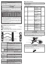
<Examples of device placement>
1) Side-by-side placement
2) Vertical placement
Emitter Emitter
Receiver
Receiver
Emitter
Receiver
Receiver
Emitter
3) Front and back placement
4) With a light-blocking barrier
Emitter
Emitter
Receiver
Receiver
Receiver
Emitter
Emitter
Receiver
Blocking object
<Reference>
If you have questions or problems, please contact our office.
WARNING
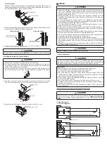
The emitter and receiver cables must be oriented in the same direction. Risk of
malfunctioning if the cables are not in the same oriented in the same direction.
Cable
Cable
Cable
Cable
7
MOUNTING
CAUTION
●
The minimum bending radius of the cables is R6mm. Keep the minimum bending
radius of the cables in mind during installation.
●
Do not apply stress such as excessive bending or pulling to the extracted part of
a cable.
●
After installing this device, be sure to adjust the beams so that the device's sta-
ble light reception indicator lights green and the number “3” lights green on the
digital indicator. To adjust the beams, refer to the manual on our website.
When using as a safety device for a press machine or paper shearing machine in Japan
(Applicable model: SF4D-□-01)
WARNING
●
When using as a safety device for a press machine or paper shearing machine
in Japan, always attach the protective tube
SFPD-A10
(option) to the cable.
●
The minimum bending radius of the cable with the protective tube
SFPD-A10
at-
tached is 55mm. Take into consideration the minimum bending radius of the ca-
ble with the protective tube
SFPD-A10
attached.
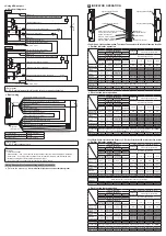
<Reference>
Mount the emitter and the receiver at the same level and parallel to each other.
The effective aperture angle of the device is ±2.5° or less for a sensing range of 3m.
<Using beam adjustment mounting bracket MS-SFD-1-5 (Option)>
1.
Insert the mounting plate of the base bracket into the base bracket mounting rail
on the back of the device.
Mounting plate
Base bracket
Base bracket mounting rail
This device
2.
With the base bracket in firm contact with the device, tighten the two ultra low-
head hex socket bolts [M5 (length 5mm), opposing faces 3mm] that fasten the
base bracket. Tighten to a torque of 3N·m or less.
No gap between base
bracket and device.
Ultra low-head hex socket bolt for base bracket
[M5 (length 5mm), opposing faces 3mm]
<Side mounting>
Loosen the two hexagon-socket head bolts with washers [M4 (length 8mm), op-
posing faces 3mm] and remove the bracket.
Change the orientation of the mounting bracket, and tighten the two hexa-
gon-socket head bolts with washers [M4 (length 8mm), opposing faces 3mm].
Tighten to a torque of 1.5N·m or less.
Hexagon-socket head bolt with washer
[M4 (length 8mm), opposing faces 3mm]
(Included with
MS-SFD-1-5
)
Mounting bracket
Base bracket
3.
Install the beam adjustment mounting bracket on the mounting surface with a
hexagon-socket head bolt (purchase separately).
Hexagon-socket head bolt
[M5 (purchase separately)]
Hexagon-socket head bolt
[M8 (purchase separately)]
<Using intermediate supporting bracket MS-SFB-2 (Option)>
1.
Loosen the hexagon-socket head bolt [M4 (length 12mm), opposing faces 3mm]
on the intermediate supporting bracket.
Hexagon-socket head bolt
[M4 (length 12mm), opposing faces 3mm]
2.
Fit the intermediate supporting bracket onto the side of the device, and fasten with
the hexagon-socket head bolt [M4 (length 12mm), opposing faces 3mm]. Tighten
to a torque of 1.2N·m or less.
This device


