S-2
S2. Voltage Chart
S2.1. Rear P.C.B.
Note) Indicated voltage values are the standard values for the unit measured by the DC electronic circuit tester (high-impedance) with the chassis taken as standard.
Therefore, there may exist some errors in the voltage values, depending on the internal impedance of the DC circuit tester.
REF No. PIN No. REC
PB
EE
IC3931
1
-
-
-
IC3931
2
-
-
-
IC3931
3
-
-
-
IC3931
4
1.4
1.4
1.4
IC3931
5
1.4
1.4
1.4
IC3931
6
1.4
1.4
1.4
IC3931
7
1.4
1.4
1.4
IC3931
8
1.4
1.4
1.4
IC3931
9
0
0
0
IC3931
10
1.4
1.4
1.4
IC3931
11
1.4
1.4
1.4
IC3931
12
1.4
1.4
1.4
IC3931
13
1.4
1.4
1.4
IC3931
14
0
0
0
IC3931
15
3
3
3
IC3931
16
-
-
-
Q3901
E
3.1
3.1
3.1
Q3901
C
0
0
0
Q3901
B
3.1
3.1
3.1
S2.2. Monitor P.C.B.
REF No. PIN No. REC
PB
EE
Q901
E
1.4
1.4
1.4
Q901
C
0
0
0
Q901
B
0.8
0.8
0.8
Содержание SDR-S70P
Страница 11: ...11 4 Specifications...
Страница 13: ...13...
Страница 14: ...14...
Страница 18: ...18 7 Service Fixture Tools 7 1 Service Tools and Equipment...
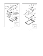
Страница 21: ...21 Fig D3 Fig D4...
Страница 24: ...24 Fig D13 Fig D14 Fig D15 Fig D16...
Страница 25: ...25 Fig D17 Fig D18 Fig D19 Fig D20...
Страница 26: ...26 Fig D21 Fig D22...
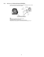
Страница 28: ...28 8 4 1 How to use of CCD positioning pin RFKZ0476...
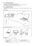
Страница 30: ...30 9 2 2 Checking and repairing individual circuit boards How to use extension cables...
Страница 31: ...31 9 3 Location for Connectors of the Main P C B 9 3 1 Main P C B...
Страница 62: ...S 26 S7 2 LCD Section 15 17 16 18 34 19 20 21 33 B17 B26 B27...


