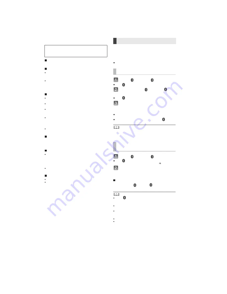
10
5 General/Introduction
5.1.
About Bluetooth and Operation
Bluetooth
®
connection
About Bluetooth
®
Frequency band used
This system uses the 2.4 GHz frequency band.
Certification of this device
This system conforms to frequency restrictions and has
received certification based on frequency laws. Thus, a
wireless permit is not necessary.
The action below are punishable by law in some
countries:
Taking apart or modifying the unit.
Removing specification indications.
Restrictions of use
Wireless transmission and/or usage with all Bluetooth
®
equipped devices is not guaranteed.
All devices must conform to standards set by Bluetooth
SIG, Inc.
Depending on the specifications and settings of a
device, it can fail to connect or some operations can be
different.
This system supports Bluetooth
®
security features. But
depending on the operating environment and/or
settings, this security is possibly not sufficient. Transmit
data wirelessly to this system with caution.
This system cannot transmit data to a Bluetooth
®
device.
Range of use
Use this device at a maximum range of 10 m (33 ft).
The range can decrease depending on the environment,
obstacles or interference.
Interference from other devices
This system may not function properly and troubles
such as noise and sound jumps may arise due to radio
wave interference if the main unit is located too close to
other Bluetooth
®
devices or the devices that use the 2.4
GHz band.
This system may not function properly if radio waves
from a nearby broadcasting station, etc. are too strong.
Intended usage
This system is for normal, general use only.
Do not use this system near equipment or in an
environment that is sensitive to radio frequency
interference (example: airports, hospitals, laboratories,
etc).
Panasonic bears no responsibility for data
and/or information that is compromised
during a wireless transmission.
-
-
By using the Bluetooth
®
connection, you can listen
to the sound from the Bluetooth
®
audio device
from this system wirelessly.
Preparation
Turn on the Bluetooth
®
feature of the device and
place the device near the main unit.
Press [
] to select “
”.
If the “
” indicator flashes quickly, go to step 3.
Press and hold [
] until the “
”
indicator flashes quickly.
If the “
” indicator flashes slowly, repeat step 2.
Select “SC-HTB70” or “SC-HTB65”
from the Bluetooth
®
device’s
Bluetooth
®
menu.
If prompted for the passkey on the Bluetooth
®
device, enter
“0000”.
Once the Bluetooth
®
device is connected, the “
” indicator
stops flashing and lights up.
You can register up to 8 devices with this system. If a 9th
device is paired, the device that has not been used for the
longest time will be replaced.
Press [
] to select “
”.
If the “
” indicator lights, a Bluetooth
®
device is already
connected with this system. Disconnect it. (
below)
Select “SC-HTB70” or “SC-HTB65”
from the Bluetooth
®
device’s
Bluetooth
®
menu.
Disconnecting a Bluetooth
®
device
Press and hold [
] until the “
” indicator flashes
slowly.
When “
” is selected as the source, this system will
automatically try and connect to the last connected
Bluetooth
®
device.
The Bluetooth
®
device will be disconnected if a different
audio source (e.g. “TV“) is selected.
Refer to the operating instructions of the Bluetooth
®
device
for further instruction on how to connect a Bluetooth
®
device.
This system can only be connected to one device at a time.
To change the sound quality, refer to “Bluetooth
®
communication mode”.
Bluetooth
®
pairing
Connecting a Bluetooth
®
device
Содержание SC-HTB70P
Страница 24: ...24 ...
Страница 28: ...28 11 2 Types of Screws 11 3 Main Parts Location Diagram ...
Страница 39: ...39 Step 4 Lift up to remove the Sub Chassis Unit ...
Страница 49: ...49 Step 8 Release 1 catch Step 9 Remove the AC Holder ...
Страница 55: ...55 Step 3 Remove 2 screws Step 4 Remove the Button Holder ...
Страница 60: ...60 11 14 2 Assembly of 6P Wire Main Button Step 1 Dressed the 6P Wire into the ribs of the Front Panel Block ...
Страница 88: ...88 Step 13 SMPS P C B and AC Inlet P C B can be checked as diagram shown ...
Страница 92: ...92 Step 17 Main P C B Side A can be checked as diagram shown ...
Страница 94: ...94 Step 13 Main P C B Side B can be checked as diagram shown ...
Страница 98: ...98 Step 17 AUX P C B and Sensor P C B can be checked as diagram shown ...
Страница 101: ...101 Step 6 LED P C B can be checked as diagram shown ...
Страница 102: ...102 ...
Страница 110: ...110 ...
Страница 132: ...132 WF No Q5504 3 PLAY 24Vp p 500nsec div WF No Q5504 5 PLAY 7 0Vp p 500nsec div ...
Страница 136: ...136 ...
Страница 140: ...140 ...


