background image

13

R

Q

T

7994

C

o

nne

ct

ion

s

Se

tt

ings

B

asic

 O

p

era

tio

n

s

Bef

o

re

 use

Ope

ra

tions

Re

fe

re

n

ce

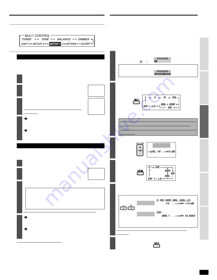
Settings - 

Test

Change these settings to suit the connections you have made to the
optical (OPT) and coaxial (COAX) digital input terminals. (

á

pages 4, 5, 9

and 10)
You can only allocate one piece of equipment per terminal.

This unit automatically detects whether input is digital or analog, but you
can fix the input mode. Select “

AUTO 

” when it is not necessary to fix the

signal.

Note regarding PCM FIX mode

In rare cases, the unit may have trouble recognizing the digital signals on discs. 
With the PCM signals on CDs, this may cause the beginning of a track to
be cut off. Engage the PCM FIX mode if this occurs. 
When PCM FIX mode is on, the unit cannot process other signals. This
may cause noise to be output. Select another mode in this case. 
• This setting is not necessary when playback is normal.
• When an input position is set to PCM FIX, and the input signals are not

from a PCM source, “

PCM FIX 

” flashes on the display.

Check that sound is output from the connected 
speakers.

• Adjust so output level from each speaker is balanced with the

output level from the front speakers.

L: Front left

 C: Center

 R: Front right 

RS: Surround right

 LS: Surround left 

SBL: Surround back left 

 SBR: Surround back right 

SB: Surround back (If you connect one surround back speaker)
SW: Subwoofer

Changing the digital input terminals

2

Select “

D-INPUT 

” (DIGITAL INPUT) and press  

[ENTER].

3

Select the input position and press  
[ENTER].

TV/STB, 
DVR, DVD, 
CD

4

Change the setting and press  
[ENTER].

Repeat steps 3 and 4 to set other input 
positions.

OPT 1, 
OPT 2, 
COAX 1, 
COAX 2

5

Select another setting

Press [MULTI CONTROL, CANCEL] several times to return to
step 2 in the operations across and select another setting. 

Finish setting

Press [MULTI CONTROL, CANCEL] several times to select

EXIT 

” and press [ENTER].

Input signal settings

2

Select “

IN MODE 

” (INPUT MODE) and press  [ENTER].

3

Select the input position and press  
[ENTER].

TV/STB, 
DVR, DVD, 
CD

4

Change the setting and press  [ENTER].

AUTO:

Automatically detects the input signal and plays. 
(In “AUTO”, the unit distinguishes the digital 
signals then the analog signals.)

ANALOG: Fixes the input signal to analog and plays.
DIGITAL: Fixes the input signal to digital and plays.
PCM FIX: Fixes the input signal to PCM and plays.

Repeat steps 3 and 4 to set other input positions.

5

Select another setting

Press [MULTI CONTROL, CANCEL] several times to return to
step 2 in the operations across and select another setting. 

Finish setting

Press [MULTI CONTROL, CANCEL] several times to select

EXIT 

” and press [ENTER].

1

Turn SPEAKERS A on.

-When using a BI-WIRE connection-

• If you select SPEAKERS B only, the test signal will not be output.

2

Check the test signal output. 

A test signal is output from one speaker at a time for two seconds
in the following order.

• Speakers set as “

_

” (not connected) in “Speakers combination

settings” (

á

page 12)  are skipped.

If there is no output from a connected speaker, 
Stop the test signal (step 6) and check the 
connections 

(

á

pages 6 to 8) 

and settings 

(

á

page 12, 

left)

 again.

3

Adjust the main volume.

4

Select the speaker channel.

5

Adjust the level.

• Adjust center, surround and surround back output to the same

apparent level as the front speakers.

• Approximately two seconds after adjusting the level, a test

signal is again output from each speaker in order. 

Repeat steps 4 and 5 to adjust the level of each 
speaker.

6

Stop the test signal.

SPEAKERS

A

B

VOL- 50dB

(MIN)

(MAX)

SW       10

C      +4dB

(MIN)

(MAX)

Factory settings: 0 dB

Factory setting: 10

Содержание SA-XR55K

Страница 1: ...ter 3 Listening caution 3 Supplied accessories 3 Connections Home Theater connections 1 TV and DVD player 4 Basic connection 4 High picture quality connection 5 DVD ANALOG 6CH connection 5 2 Speakers 6 Bi wiring connection 8 Using speaker terminal B 8 3 AC power supply cord 8 Other connections DVD recorder 9 VCR 9 Cable box or satellite receiver etc 10 CD player 10 Tape deck 10 Game player etc 10 ...

Страница 2: ...IDS SUCH AS VASES SHALL BE PLACED ON THE APPARATUS CAUTION RISK OF ELECTRIC SHOCK DO NOT OPEN CAUTION TO REDUCE THE RISK OF ELECTRIC SHOCK DO NOT REMOVE SCREWS NO USER SERVICEABLE PARTS INSIDE REFER SERVICING TO QUALIFIED SERVICE PERSONNEL The lightning flash with arrowhead symbol within an equilateral triangle is intended to alert the user to the presence of uninsulated dangerous voltage within t...

Страница 3: ...t your equipment offers This manufacturer and the Electronic Industries Association s Consumer Electronics Group want you to get the most out of your equipment by playing it at a safe level One that lets the sound come through loud and clear without annoying blaring or distortion and most importantly without affecting your sensitive hearing We recommend that you avoid prolonged exposure to excessi...

Страница 4: ...R COAXIAL2 OPTICAL2 TV MONITOR DVD TV MONITOR DVD RECORDER DVD RECORDER COMPONENT VIDEO DVD TV MONITOR PB PR Y PB PR Y PB PR Y PB PR SURROUND SUBWOOFER CENTER DVD DVD 6CH AUDIO AUDIO LOOP EXT GND AUDIO OPTICAL1 TV STB OUT IN TV STB DIGITAL IN TV MONITOR VIDEO DVD COAXIAL1 IN DVD DVD DVD 6CH FRONT Changing the digital input settings You can change the input settings for the digital terminals if nec...

Страница 5: ...O DIGITAL IN AM ANT FM ANT CD SUBWOOFER VCR1 DVD RECORDER COAXIAL2 OPTICAL2 TV MONITOR DVD RECORDER DVD RECORDER Y PB PR SURROUND SUBWOOFER CENTER DVD DVD 6CH AUDIO AUDIO LOOP EXT GND AUDIO OPTICAL1 TV STB OUT IN TV STB IN TV STB DIGITAL IN TV MONITOR DVD COAXIAL1 IN DVD DVD DVD 6CH FRONT OUT TV MONITOR Y PB PR IN DVD Y PB PR Y IN TV STB PR PB OUT TV MONITOR IN DVD IN TV STB VIDEO COMPONENT VIDEO ...

Страница 6: ... The front center surround and surround back speakers should be placed at approximately the same distance from the seating position The angles in the diagram are approximate Set the distance of the speakers from the seating position if you cannot place them at the same distances ápage 21 Speaker settings and placement should suit the number of speakers ápage 12 The number of speakers Speakers Plac...

Страница 7: ...CK SURROUND CENTER FRONT B FRONT A LF HF R L R L BI WIRE R L R L AC IN SURROUND BACK SURROUND CENTER FRONT A LF R L BI WIRE R L R L L R DVD RECORDER TV STB LOOP ANT GND REC OUT IN OUT TA DIGITAL IN AM ANT FM ANT CD SUBWOOFER OPTICAL2 OPTICAL1 LOOP EXT GND OUT SUBWOOFER Center speaker Front speakers R L Speaker impedance Front A 6 8 Ω Center 6 8 Ω Surround 6 8 Ω Surround back 6 8 Ω Surround speaker...

Страница 8: ...áRefer to page 14 for Using SPEAKERS B Connect this cord after all other cables and cords are connected Note The included AC power supply cord is for use with this unit only Do not use it with other equipment Do not use an AC power supply cord from any other type of equipment with this unit If the unit is left unplugged for longer than two weeks all settings will revert to the factory settings Per...

Страница 9: ...TICAL2 AUDIO DIGITAL AUDIO OUT AUDIO OUT AUDIO IN VIDEO OUT VIDEO IN You can change the input settings for the digital terminals if necessary Note the equipment you have connected to the terminals then change the settings ápage 13 DVD recorder R L R L Y IN IN IN IN IN IN IN OUT OUT TV STB TV STB TV STB VCR1 DVD RECORDER DVD TV MONITOR DVD PB PR PB PR VIDEO IN DVD RECORDER Y PB PR IN S VIDEO DVD RE...

Страница 10: ...N OUT DVD DVD RECORDER TV STB LOOP ANT GND CD OUT IN IN IN IN IN IN IN OUT OUT TV STB TV S TV STB IN IN OUT PLAY IN REC OUT IN OUT VCR1 DVD RECORDER TAPE VIDEO S VIDEO DIGITAL IN AM ANT FM ANT CD SUBWOOFER VCR1 DVD RECORDER DVD COAXIAL2 COAXIAL1 OPTICAL2 OPTICAL1 TV MONITOR DVD TV MONITOR DVD RECORDER DVD RECORDER COMPONENT VIDEO DVD TV MONITOR PB PR Y PB PR Y PB PR Y PB PR IN TV STB FRONT SURROUN...

Страница 11: ...OAXIAL2 COAXIAL1 OPTICAL2 OPTICAL1 TV MONITOR DV TV MONITOR Y P Y PB PR FRONT SURROUND SUBWOOFER CENTER DVD DVD 6CH AUDIO LOOP EXT GND LOOP ANT GND AM ANT FM ANT LOOP EXT GND LOOP ANT GND AM ANT FM ANT LOOP EXT GND 1 2 2 1 3 LOOP ANT GND FM ANT 75Ω GND 1 2 Black Red Adhesive tape White FM outdoor antenna not included Disconnect the FM indoor antenna The antenna should be installed by a competent t...

Страница 12: ...he MULTI CONTROL Select SETUP 1 BASIC SETUP scrolls once and press ENTER Select the settings to change ábelow page 13 Speakers combination settings 2 Select SPKR SET SPEAKER SET and press ENTER 3 Select if you have connected a subwoofer or not and press ENTER SUBW NO You have not connected one SUBW YES You have connected one 4 Select the speaker combination connected to this unit and press ENTER L...

Страница 13: ...OL CANCEL several times to return to step 2 in the operations across and select another setting Finish setting Press MULTI CONTROL CANCEL several times to select EXIT and press ENTER Input signal settings 2 Select IN MODE INPUT MODE and press ENTER 3 Select the input position and press ENTER TV STB DVR DVD CD 4 Change the setting and press ENTER AUTO Automatically detects the input signal and play...

Страница 14: ... MIX is displayed and the sounds intended for all the speakers are played through the front speakers When DVD ANALOG 6CH is selected the sound from the front 2 channels is output If you select SPEAKERS B only the following are set automatically irrespective of settings selected in speaker settings ápages 12 21 Speaker size LARGE Subwoofer NO Bass is output from the front speakers n Using headphone...

Страница 15: ...ancel n You can make further adjustments to the effect of MUSIC mode ápage 18 S Using the Sound Field Control SFC Select LIVE Imparts the reflection and spread of a large concert hall POP ROCK Best suited for dynamic sound such as pop and rock music VOCAL Best suited to enhance vocals JAZZ Recreates natural sound ambience and direction DANCE Enjoy a dance hall like audio effect Select DRAMA Best s...

Страница 16: ...annels contained in the digital input signal light No sound is output from a channel if the speaker is set to _ not connected in Speakers combination settings ápage 12 even if the channel indicator lights L Front left channel C Center channel R Front right channel LS Surround left channel SB Surround back channel RS Surround right channel S If the surround channel is monaural LFE Low Frequency Eff...

Страница 17: ... EX MUSIC or GAME when Dolby Pro Logic mode or Dolby Pro Logic mode is on DTS NEO 6 For selecting a DTS NEO 6 mode CINEMA or MUSIC SFC MUSIC For selecting a SFC mode LIVE POP ROCK VOCAL JAZZ or DANCE SFC AV MOVIE For selecting a SFC mode DRAMA ACTION SPORTS MUSICAL or GAME OFF To cancel surround effects TEST To start the speaker test signal LEVEL To adjust speaker level EFFECT To adjust Dolby Pro ...

Страница 18: ...n make up for differences in the output level of the front and surround speakers You can choose a level between 3 and 3 Increase the level to move sound to the front speakers decrease to move it to the surround speakers Select Adjust C WDTH Center Width Control This adjustment helps you realize a more natural sound image when listening to music Move sound out into the front speakers to improve the...

Страница 19: ...ows the standard balance Changing the audio output Dual program When the input signal is Dolby Digital DTS and DUAL appears in the display the audio to be output is set 2 Select OPTION and press ENTER 3 Select DUAL PRG DUAL PROGRAM and press ENTER 4 Select the audio and press ENTER MAIN Main audio output SAP Sub channel audio output MAIN SAP Main and sub channel audio output 5 Select another setti...

Страница 20: ...NG IS ON scrolls on the display while the volume is muted Muting is canceled when the power is turned off n To cancel Press again Multi source re master This original feature boosts the frequencies of the higher harmonics that are lost during recording due to compression You can enjoy a full more natural sound with this Select Dolby Pro Logic DTS NEO 6 and SFC are canceled when using multi source ...

Страница 21: ...ONT CENTER SURROUND SUR BACK 4 Change the setting and press ENTER SUB WFR NO YES FRONT SMALL LARGE CENTER SURROUND NONE SMALL LARGE SUR BACK NONE 1 SPKR 2 SPKRS NONE For speakers you haven t connected center surround or surround back SMALL For speakers that cannot adequately reproduce the bass range This setting is sufficient for most speakers if you are using a subwoofer LARGE For speakers that c...

Страница 22: ...R ENTER CANCEL MULTI CONTROL TUNE PRESET BAND INPUT SELECTOR ENTER CANCEL MULTI CONTROL Manual Tuning n On the remote control Direct tuning 1 Select TUNER 2 Select FM or AM Press and hold for 2 seconds 3 Press DISC DIRECT TUNING 4 Enter the station frequency e g 107 9 MHz Press 1 0 7 9 Tuning intervals FM 0 1 MHz AM 10 kHz If you do not press a button while the cursor is flashing the display retur...

Страница 23: ... operations with the MULTI CONTROL 3 Select TUNER and press ENTER 4 Select MEMORY and press ENTER 5 Select a channel number and press ENTER STORED is displayed To continue presetting press TUNE 2 or 1 to tune another station from step 1 6 Press MULTI CONTROL CANCEL 2 times to select EXIT and press ENTER Even if the AC power supply cord is disconnected from the household AC outlet the stations rema...

Страница 24: ...ss ENTER 6 Press TUNER BAND 7 Press and hold both at the same time for 2 seconds n To return to REM1 1 Select REM1 in step 4 2 Press and hold both ENTER and 1 at the same time for 2 seconds in step 7 INPUT SELECTOR ENTER CANCEL MULTI CONTROL CANCEL MULTI CONTROL Main menu Sub menu factory settings Pages Main menu Sub menu factory settings Pages TUNER 1 FM MODE 2 AUTO 23 SETUP 1 BASIC SETUP SPKR SE...

Страница 25: ...TV DVD DVD RECORDER Output TV MONITOR n GENERAL Power supply AC 120 V 60 Hz Power consumption 135W Dimensions W x H x D 430 mm x 107 5 mm x 394 mm 16 15 16 x 4 7 32 x 15 1 2 Mass 4 6 kg 10 1 lb n DIN POWER 1 kHz T H D 1 2 x 100 W 6 Ω Notes 1 Specifications are subject to change without notice Mass and dimensions are approximate 2 Total harmonic distortion is measured by the digital spectrum analyz...

Страница 26: ...26 RQT7994 Connections Settings Basic Operations Operations Before use Reference Warranty U S A ...

Страница 27: ...rchase is required before warranty service is performed THIS EXPRESS LIMITED WARRANTY IS IN LIEU OF ALL OTHER WARRANTIES EXPRESS OR IMPLIED INCLUDING ANY IMPLIED WARRANTIES OF MERCHANTABILITY AND FIT NESS FOR A PARTICULAR PURPOSE IN NO EVENT WILL PANASONIC CANADA INC BE LIABLE FOR ANY SPECIAL INDIRECT OR CONSEQUENTIAL DAMAGES In certain instances some jurisdictions do not allow the exclusion or li...

Страница 28: ...ch the Remote control mode on the main unit and the remote control 24 Display is dim Cancel DIMMER 19 20 Clicking sound heard during play Depending on the input signal when playing DVD etc the DUAL AMP function changes automatically A clicking sound is heard when it changes This does not mean a problem with the unit 15 n Surround effects Pages Sound is not heard from the center surround or subwoof...

Отзывы: