86
11 Service Positions
Note: For description of the disassembly procedures, see
the Section 9.
11.1. Checking and Repairing of
Main P.C.B.
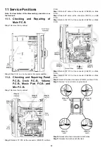
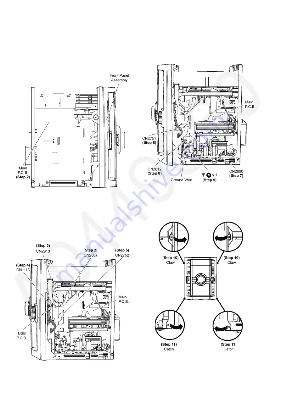
Step 1 Remove the top cabinet .
Step 2 Main P.C.B. can be checked at its original position.
11.2. Checking and Repairing Panel
P.C.B., Deck P.C.B., Volume
P.C.B., Music Port P.C.B. and
Mic P.C.B.
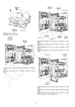
Step 1 Remove the top cabinet.
Step 2 Detach 27P FFC at the connector (CN2807) on Main
P.C.B..
Step 3 Detach 2P cable at the connector (CN2813) on Main
P.C.B..
Step 4 Detach 5P cable at the connector (CN1113) on USB
P.C.B..
Step 5 Detach 10P FFC at the connector (CN2752) on Main
P.C.B..
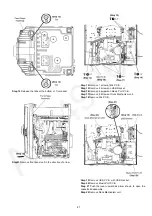
Step 6 Detach 12P FFC at the connector (CN2751) on Main
P.C.B..
Step 7 Detach 10P FFC at the connector (CN2806) on Main
P.C.B..
Step 8 Detach 2P cable at connector (CN2812) on Main P.C.B..
Step 9 Remove 1 screw to remove ground wire.
Step 10 Release the claws outwards on both sides.
Step 11 Release the catches at both sides.
Содержание SA-VK680EE
Страница 13: ...13 ...
Страница 48: ...48 ...
Страница 50: ...50 9 2 Main Components and P C B Location ...
Страница 116: ...116 ...
Страница 118: ...118 ...
Страница 144: ...144 ...

