


16.1. Disassembly steps
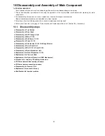
16 Disassembly and Assembly of Main Component
“ATTENTION SERVICER”
Some chassis components may have sharp edges. Be careful when disassembling and servicing.
1. This section describes procedures for checking the operation of the major printed circuit boards and replacing the main
components.
2. For reassembly after operation checks or replacement, reverse the respective procedures.
Special reassembly procedures are described only when required.
3. Select items from the following index when checks or replacement are required.
4. Refer to the Parts No. on the page of “Parts Location and Replacement Parts List” (Section 26), if necessary.
•
•
•
•
Disassembly of Top Cabinet
•
•
•
•
Disassembly of Rear Panel
•
•
•
•
Disassembly of DVD Changer Unit
•
•
•
•
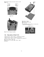
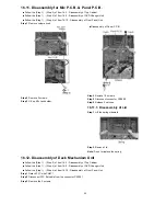
Disassembly of Main P.C.B.
•
•
•
•
Disassembly of Sub-Power P.C.B.
•
•
•
•
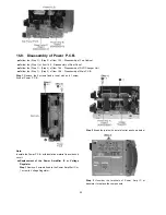
Disassembly of Power P.C.B.
•
•
•
•
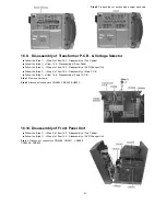
Disassembly of Transformer P.C.B. & Voltage Selector
•
•
•
•
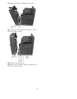
Disassembly of Front Panel Unit
•
•
•
•
Disassembly of Mic P.C.B. & Panel P.C.B.
•
•
•
•
Disassembly of Deck Mechanism Unit
•
•
•
•
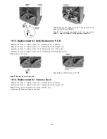
Replacement for Deck Mechanism P.C.B.
•
•
•
•
Replacement for Traverse Deck
•
•
•
•
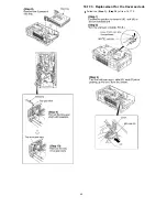
Replacement for Optical Pickup Unit (DVD Mechanism)
•
•
•
•
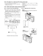
Procedure for removing CD loading mechanism
•
•
•
•
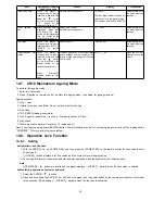
CR16 mechanism disassembly procedure
•
•
•
•
CR16 mechanism assembly procedure
•
•
•
•
Disassembly for Traverse Unit
•
•
•
•
Replacement for cassette lid ass’y
•
•
•
•
Rectification for tape jam problem
25
Содержание SA-TM900DVD
Страница 9: ...10 Operation Procedures 9 ...
Страница 10: ...10 ...
Страница 11: ...11 Disc information 11 ...
Страница 12: ...12 ...
Страница 15: ...15 ...
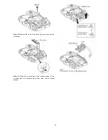
Страница 35: ...Step 2 Remove DVD traverse deck by rotating to the arrow direction 35 ...
Страница 39: ...39 ...
Страница 40: ...16 17 3 Replacement for the traverse deck Follow the Step 1 Step 10 of item 16 17 2 40 ...
Страница 42: ...42 ...
Страница 43: ...43 ...
Страница 45: ...45 ...
Страница 46: ...46 ...
Страница 47: ...47 ...
Страница 48: ...48 ...
Страница 49: ...49 ...
Страница 50: ...50 ...
Страница 51: ...51 ...
Страница 52: ...52 ...
Страница 53: ...53 ...
Страница 54: ...54 ...
Страница 55: ...55 ...
Страница 65: ...18 3 1 Cassette Deck Section 18 3 2 Adjustment Point 18 3 Alignment Points 65 ...
Страница 77: ...20 Voltage Measurement This section is not available at time of issue 77 ...
Страница 102: ...6CC 6CC 54 4 4 54 6CC 2 2 6 6CC 2 54 54 4 6 7 7 7 7 0 0 0 0 23 0 2 2 2 2 1 1 1 2 2 2 2 2 2 2 2 2 2 2 2 2 2 6 4 54 4 2 ...
Страница 103: ... 54 2 352 4 352 2 35 7 2 54 7 54 6CC 2 54 2 7 7 7 7 9 9 2 3 6 4 2 2 2 2 2 2 7 7 2 2 2 2 2 2 2 2 2 2 2 2 7 7 2 ...
Страница 107: ...35 6 6 7 7 7 7 7 7 6 U 2 2 2 0 2 1 2 2 1 2 2 1 2 1 2 2 2 4 6 35 ...
Страница 109: ...0 7 7 7 2 2 2 3 4 6 EW ODEL GT IC OTE ATERIAL 3IZE MODIFIED 0 4 25 ...
Страница 110: ...2 0 7 2 0 5NIT MM 0ARTS NO AME PPROVED HECKED 3 ...
Страница 111: ......
Страница 112: ......
Страница 113: ......
Страница 114: ......
Страница 115: ......
Страница 116: ...116 ...
Страница 117: ...117 ...
Страница 135: ...B0ACCK000005 MA2J72800L Cathode Anode Ca A B0AACK000004 MA2C16500E B0JAPG000019 A Ca Cathode Anode 135 ...
Страница 139: ...26 1 Deck Mechanism RAA3413 S 26 1 1 Deck Mechanism Parts Location 139 ...
Страница 140: ...140 ...
Страница 142: ...26 2 DVD Loading Mechanism 26 2 1 DVD Loading Mechanism Parts Location 142 ...
Страница 143: ...143 ...
Страница 145: ...26 3 Cabinet 26 3 1 Cabinet Parts Location 145 ...
Страница 146: ...146 ...
Страница 147: ...147 ...
Страница 188: ...3 Connection of the Wiring Diagram 4 Cabinet Parts Location 5 service m speaker 11 ...
Страница 192: ...3 Connection of the Wiring Diagram 9 service m speaker ...
Страница 193: ...4 Cabinet Parts Location 3 10 service m speaker ...
Страница 196: ...Step 1 Detach the black and blue wires from Woofer Step 2 Remove 4 screws from Woofer 13 service m speaker ...
Страница 198: ...3 Connection of the Wiring Diagram 4 Cabinet Parts Location 15 service m speaker ...
Страница 203: ...3 Connection of the Wiring Diagram 4 Cabinet Parts Location 20 service m speaker ...


