


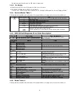

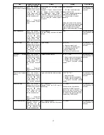


14 Self-Diagnosis Function
This unit is equipped with the self-diagnosis function, which displays an error when it occurs, for use during servicing.
14.1. Entering into Self-Diagnostic Mode
14.2. Automatic Displayed Error Codes
14.2.1. Automatic Display Function
For a power unit error, the code is automatically displayed.
F61:
Automatically displayed on the LCD of the player.
14.2.2. Re-Display
•
•
•
•
For F61 Display
−
−
−
−
When the code, F61 is displayed, the power is automatically turned off.
−
−
−
−
The code, F61 is displayed for three seconds, and then the current time appears.
−
−
−
−
To retrieve the code, turn on the power button so that the code F61 appears, however, is switched to time display after three
seconds, and the power is automatically turned off.
•
•
•
•
For F76 Display
−
−
−
−
The abnormalities is an output or the abnormalities in a power supply of POWER AMP IC.
14.2.3. Description of Error Code
14.2.3.1. F61
•
•
•
•
State, Condition
When the power is turned on, the unit is automatically turned off. The power does not turn on.
•
•
•
•
Cause, Troubleshooting
Power circuit system failure and/or direct current flown to speaker terminal
Identify the cause and replace with new parts.
14.3. Memorized Error Codes
14.3.1. Activating Self-Diagnosis Function and Displaying Method
1. Turn on the power.
2. Select DVD/CD function. With no DVD/CD inserted in the player, press and hold down the
button for at least two seconds,
and press the “0” button on the remote control for at least two seconds in order to display “DVD_F---”.
3. Press the
button. If a memorized error is detected, the result of self diagnosis is displayed. (Ex.: T H15)
18
Содержание SA-TM900DVD
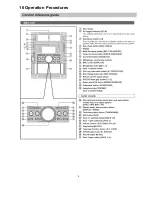
Страница 9: ...10 Operation Procedures 9 ...
Страница 10: ...10 ...
Страница 11: ...11 Disc information 11 ...
Страница 12: ...12 ...
Страница 15: ...15 ...
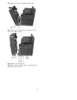
Страница 35: ...Step 2 Remove DVD traverse deck by rotating to the arrow direction 35 ...
Страница 39: ...39 ...
Страница 40: ...16 17 3 Replacement for the traverse deck Follow the Step 1 Step 10 of item 16 17 2 40 ...
Страница 42: ...42 ...
Страница 43: ...43 ...
Страница 45: ...45 ...
Страница 46: ...46 ...
Страница 47: ...47 ...
Страница 48: ...48 ...
Страница 49: ...49 ...
Страница 50: ...50 ...
Страница 51: ...51 ...
Страница 52: ...52 ...
Страница 53: ...53 ...
Страница 54: ...54 ...
Страница 55: ...55 ...
Страница 65: ...18 3 1 Cassette Deck Section 18 3 2 Adjustment Point 18 3 Alignment Points 65 ...
Страница 77: ...20 Voltage Measurement This section is not available at time of issue 77 ...
Страница 102: ...6CC 6CC 54 4 4 54 6CC 2 2 6 6CC 2 54 54 4 6 7 7 7 7 0 0 0 0 23 0 2 2 2 2 1 1 1 2 2 2 2 2 2 2 2 2 2 2 2 2 2 6 4 54 4 2 ...
Страница 103: ... 54 2 352 4 352 2 35 7 2 54 7 54 6CC 2 54 2 7 7 7 7 9 9 2 3 6 4 2 2 2 2 2 2 7 7 2 2 2 2 2 2 2 2 2 2 2 2 7 7 2 ...
Страница 107: ...35 6 6 7 7 7 7 7 7 6 U 2 2 2 0 2 1 2 2 1 2 2 1 2 1 2 2 2 4 6 35 ...
Страница 109: ...0 7 7 7 2 2 2 3 4 6 EW ODEL GT IC OTE ATERIAL 3IZE MODIFIED 0 4 25 ...
Страница 110: ...2 0 7 2 0 5NIT MM 0ARTS NO AME PPROVED HECKED 3 ...
Страница 111: ......
Страница 112: ......
Страница 113: ......
Страница 114: ......
Страница 115: ......
Страница 116: ...116 ...
Страница 117: ...117 ...
Страница 135: ...B0ACCK000005 MA2J72800L Cathode Anode Ca A B0AACK000004 MA2C16500E B0JAPG000019 A Ca Cathode Anode 135 ...
Страница 139: ...26 1 Deck Mechanism RAA3413 S 26 1 1 Deck Mechanism Parts Location 139 ...
Страница 140: ...140 ...
Страница 142: ...26 2 DVD Loading Mechanism 26 2 1 DVD Loading Mechanism Parts Location 142 ...
Страница 143: ...143 ...
Страница 145: ...26 3 Cabinet 26 3 1 Cabinet Parts Location 145 ...
Страница 146: ...146 ...
Страница 147: ...147 ...
Страница 188: ...3 Connection of the Wiring Diagram 4 Cabinet Parts Location 5 service m speaker 11 ...
Страница 192: ...3 Connection of the Wiring Diagram 9 service m speaker ...
Страница 193: ...4 Cabinet Parts Location 3 10 service m speaker ...
Страница 196: ...Step 1 Detach the black and blue wires from Woofer Step 2 Remove 4 screws from Woofer 13 service m speaker ...
Страница 198: ...3 Connection of the Wiring Diagram 4 Cabinet Parts Location 15 service m speaker ...
Страница 203: ...3 Connection of the Wiring Diagram 4 Cabinet Parts Location 20 service m speaker ...


