
Pickup
Beam source / wavelength
Semiconductor laser / 780nm
Number of channels
Stereo
Wow and flutter
Below measurable limit
Digital filter
8 fs
D/A converter
MASH (1 bit DAC)
Frequency response
20Hz - 20 kHz (+1dB, -2dB)
n
General
Power supply
AC 120 V, 60 Hz
Power consumption
57 W
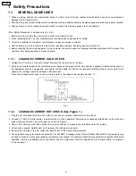
1 Safety Precautions
4
1.1.
GENERAL GUIDELINES
4
2 Before Repair and Adjustment
6
3 Protection Circuitry
6
4 Handling the Lead-free Solder
6
4.1.
About lead free solder (PbF)
6
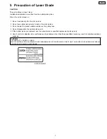
5 Precaution of Laser Diode
7
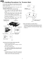
6 Handling Precautions For Traverse Deck
8
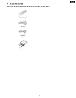
7 Accessories
9
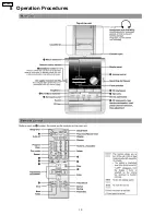
8 Operation Procedures
10
9 Information on CD & MP3
11
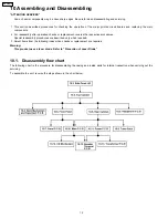
10 Assembling and Disassembling
12
10.1. Disassembly flow chart
12
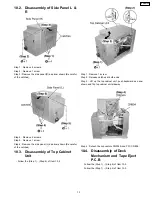
10.2. Disassembly of Side Panel L & R
13
10.3. Disassembly of Top Cabinet Unit
13
10.4. Disassembly of Deck Mechanism and Tape Eject P.C.B 13
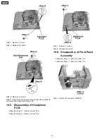
10.5. Disassembly of Headphone P.C.B
14
10.6. Disassembly of Front Panel Assembly
14
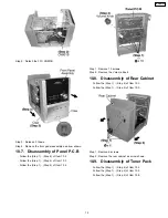
10.7. Disassembly of Panel P.C.B
15
10.8. Disassembly of Rear Cabinet
15
10.9. Disassembly of Tuner Pack
15
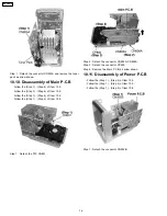
10.10. Disassembly of Main P.C.B
16
10.11. Disassembly of Power P.C.B
16
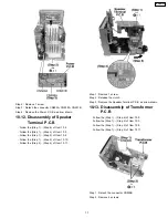
10.12. Disassembly of Speaker Terminal P.C.B
17
10.13. Disassembly of Transformer P.C.B
17
10.14. Disassembly of CD Mechanism
18
10.15. Checking Procedure for Each Major P.C.B.
19
10.16. Procedures of Replacing Traverse Base (Unit), Driving
Gear, and Cam Gear (CD Mechanism Unit)
19
10.17. Procedures for Replacing Optical Pickup (CD Mechanism
Unit)
22
10.18. Procedures for Replacement Traverse Gear A and
Traverse Gear B (CD Mechanism Unit)
23
Dimensions (W x H x D)
165 x 228 x 315.6 mm
(6 1/2” x 9” x 12 7/16”)
Mass
3.6 kg (7.9 Ibs)
Power consumption in standby
mode
0.5 W
Notes :
1. Specifications are subject to change without notices. Mass and
dimensions are approximate.
2. Total harmonic distortion is measured by the digital spectrum
analyzer.
n
System : SC-PM21PC-S
Music center: SA-PM21PC-S
Speaker: SB-PM21E-MJ
10.19. Procedure for Replacing Cassette Holder
24
10.20. Procedure for Replacing Pinch Roller and Head Block
(Deck Mechanism Unit)
24
10.21. Procedure for Replacing Motor, Capstan Belt A, Capstan
Belt B, and Winding Belt (Deck Mechanism Unit)
25
10.22. Procedure for Replacing Parts on Deck Mechanism PCB
27
10.23. Handling of cassette tape jam
27
11 Service Positions
29
11.1. Checking procedure
29
11.2. Checking the major P.C.B.
29
12 Self Diagnostic Function
30
12.1. Self-diagnosis Function
30
12.2. Clearing all error code
32
12.3. Cancelling the Self-Diagnostic mode
32
12.4. Setting of doctor mode
32
13 Procedure for Checking Operation of Individual Parts of Deck
Mechanism Unit
37
13.1. Operation Check with Cassette Tape
37
13.2. Operation Check without Cassette Tape
37
14 Measurement And Adjustments
39
14.1. Cassette Deck Section
39
15 Voltage Measurement and Waveform Chart
41
15.1. Voltage Measurement
41
15.2. Waveform
43
16 Block Diagram
44
16.1. CD Servo Block
44
16.2. Main Block
46
17 Notes of Schematic Diagram
50
18 Schematic Diagram
51
18.1. CD Servo Circuit
51
18.2. Main Circuit and Tuner Extent Circuit
53
18.3. Panel Circuit
57
CONTENTS
Page
Page
2
SA-PM21PC
Содержание SA-PM21PC
Страница 5: ...1 1 3 Caution for fuse replacement 5 SA PM21PC ...
Страница 10: ...8 Operation Procedures 10 SA PM21PC ...
Страница 11: ...9 Information on CD MP3 11 SA PM21PC ...
Страница 20: ...20 SA PM21PC ...
Страница 21: ...21 SA PM21PC ...
Страница 26: ...26 SA PM21PC ...
Страница 28: ...28 SA PM21PC ...
Страница 38: ...Fig 7 38 SA PM21PC ...
Страница 76: ...23 Troubleshooting Flowchart CD Section Circuit 76 SA PM21PC ...
Страница 77: ...77 SA PM21PC ...
Страница 79: ...24 1 Deck Mechanism 24 1 1 Deck Mechanism Parts Location RAA4402 S 79 SA PM21PC ...
Страница 81: ...24 2 CD Loading Mechanism 24 2 1 CD Loading Mechanism Parts Location 81 SA PM21PC ...
Страница 83: ...24 3 Cabinet 24 3 1 Cabinet Parts Location 83 SA PM21PC ...
Страница 84: ...84 SA PM21PC ...