


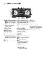

8.4. Self-Diagnostic Mode
8.5. Self-Diagnostic Error Code Table
8.6. Sales Demonstration Lock Function
9 Troubleshooting Guide
10 Disassembly and Assembly Instructions
10.1. Screw Types
10.2. Disassembly Flow Chart
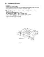
10.3. Main Components and P.C.B. Locations
10.4. Disassembly of Top Cabinet
10.5. Disassembly of Front Panel Unit
10.6. Disassembly of FL Display P.C.B.
10.8. Disassembly of Control P.C.B.
10.10. Disassembly of Volume P.C.B.
10.11 Disassembly of Volume Jog Led
10.12. Disassembly of Remote Sensor P.C.B.
10.13. Disassembly of USB P.C.B.
10.14. Disassembly of Mic P.C.B.
10.16. Disassembly of CD Lid
10.17. Disassembly of Rear Panel
10.18. Disassembly of CD Mechanism Unit
10.19. Disassembly of Main P.C.B.
10.20. Disassembly of Digital Amplifier IC
I
10.21. Disassembly of SMPS P.C.B.
10.22. Replacement of Switching Regulator (Q5700)
10.23. Replacement of Rectifier Diode (D5801)
10.24. Replacement of Rectifier Diode (D5802)
10.25. Disassembly of CD Interface P.C.B.
11 Service Position
11.1. Checking and Repairing of FL Display P.C.B.,
Control P.C.B., Volume P.C.B., Mic P.C.B. and
USB P.C.B.
11.2. Checking and Repairing of Main P.C.B. (Side
B)
11.3. Checking and Repairing of Main P.C.B. (Side
A)
11.4. Checking and Repairing of SMPS P.C.B.
12 Block Diagram
12.1. Servo & System Control
12.2. IC Terminal Chart
12.3. Audio
12.4. Power Supply
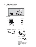
13 Wiring Connection Diagram
14 Schematic Diagram
14.1. Schematic Diagram Notes
14.2. MAIN (CD Servo/Micon/D-Amp) Circuit
14.3. FL Display Circuit
14.4. Volume Circuit
14.5. Control & USB Circuit
14.6. Mic Circuit
14.7. Remote Sensor
14.8. SMPS Circuit
14.9. Control Jog LED, Volume Jog LED & CD
Interface Circuit
15 Printed Circuit Board
15.1. Main P.C.B.
15.2. FL Display & Volume P.C.B.
15.3. Control, Mic, USB, Remote Sensor.
15.4. SMPS
15.5. Control Jog LED, Volume Jog LED & CD
Interface P.C.B.
16 Appendix Information of Schematic Diagram
16.1. Voltage & Waveform Chart
16.2. Illustration of ICs, Transistor and Diode
16.3. Terminal Function of ICs
17 Exploded View and Replacement Parts List
17.1. Exploded View and Mechanical replacement
Part List
17.2. Electrical Replacement Part List
Содержание SA-MAX500LMK
Страница 14: ...5 General Introduction 5 1 Media Information ...
Страница 26: ...9 1 2 Main P C B Front Side Fig 2 Main P C B Front Side Regulator Circuit IC2014 ...
Страница 27: ...Fig 3 Main P C B Back Side ...
Страница 30: ...9 3 D Amp IC Operation Control MAX500 ...
Страница 34: ......
Страница 36: ...10 3 Main Components and P C B Locations SMPS P C B ...
Страница 84: ...14 3 FL Display Circuit MAX500 ...
Страница 85: ...14 4 Volume Circuit MAX500 ...
Страница 86: ...MAX500 14 5 Control USB Circuit ...
Страница 87: ...14 7 Remote Sensor MAX500 ...
Страница 88: ...MAX500 ...
Страница 89: ... Jog Board MAX500 ...
Страница 90: ...Internal Fan MAX500 ...
Страница 94: ...1 1 2 3 4 5 6 7 8 9 A B C D E F G H 10 1 12 13 A MAIN P C B RD DAK110 PX SA MAX500 MAIN P C B SIDE B ...
Страница 124: ...17 1 3 Mechanical Replacement Part List ...
Страница 127: ...17 2 Electrical Replacement Part List ...


