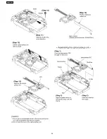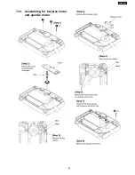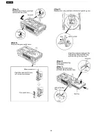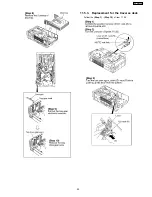
9 Handling Precautions for Optical Pickup Unit
The laser diode in the optical pickup unit may break down due to static electricity of clothes or human body. Special care must be
taken avoid to electrostatic breakdown when servicing and handling the laser diode.
9.1. Cautions to Be Taken in Handling the Optical Pickup Unit
The laser diode in the optical pickup unit may be damaged due to electrostatic discharge generating from clothes or human body.
Special care must be taken avoid to electrostatic discharge damage when servicing the laser diode.
1. Do not give a considerable shock to the optical pickup unit as it has an extremely high-precise structure.
2. To prevent the laser diode from the electrostatic discharge damage, the flexible cable of the optical pickup unit removed from
the PCB should be short-circuited with a short pin or a clip.
3. The flexible cable may be cut off if an excessive force is applied to it. Use caution when handling the flexible cable.
4. The antistatic FPC is connected to the new optical pickup unit. After replacing the optical pickup unit and connecting the flexible
cable, cut off the antistatic FPC.
9.2. Cautions to Be Taken When Replacing the Optical Pickup
The flexible cable of the optical pickup unit which was supplied as a component is equipped with a short clip to prevent the laser
diode from being damaged due to electrostatic discharge. Remove the short clip before connecting the flexible cable and make
sure that the short land is open. (If the flexible cable is short-circuited, remove the solder.)
9.3. Grounding for electrostatic breakdown prevention
Some devices such as the DVD player use the optical pickup (laser diode) and the optical pickup will be damaged by static
electricity in the working environment. Proceed servicing works under the working environment where grounding works is
completed.
9.3.1. Worktable grounding
1. Put a conductive material (sheet) or iron sheet on the area where the optical pickup is placed, and ground the sheet.
15
SA-HT680PL
Содержание SA-HT680PL
Страница 18: ...10 2 Main Components and P C B Locations 18 SA HT680PL ...
Страница 23: ...23 SA HT680PL ...
Страница 24: ...24 SA HT680PL ...
Страница 25: ...11 3 Assembling for traverse motor and spindle motor 25 SA HT680PL ...
Страница 26: ...26 SA HT680PL ...
Страница 28: ...28 SA HT680PL ...
Страница 29: ...11 5 3 Replacement for the traverse deck Follow the Step 1 Step 10 of item 11 5 2 29 SA HT680PL ...
Страница 31: ...31 SA HT680PL ...
Страница 32: ...32 SA HT680PL ...
Страница 34: ...34 SA HT680PL ...
Страница 35: ...35 SA HT680PL ...
Страница 36: ...36 SA HT680PL ...
Страница 37: ...37 SA HT680PL ...
Страница 38: ...38 SA HT680PL ...
Страница 39: ...39 SA HT680PL ...
Страница 40: ...40 SA HT680PL ...
Страница 41: ...41 SA HT680PL ...
Страница 42: ...42 SA HT680PL ...
Страница 43: ...43 SA HT680PL ...
Страница 44: ...44 SA HT680PL ...
Страница 46: ...46 SA HT680PL ...
Страница 52: ...52 SA HT680PL ...
Страница 58: ...58 SA HT680PL ...
Страница 66: ...SA HT680PL 66 ...
Страница 72: ...SA HT680PL 72 ...
Страница 88: ...SA HT680PL 88 ...
Страница 90: ...SA HT680PL 90 ...
Страница 94: ...27 1 Loading Mechanism Traverse Unit Cabinet 94 SA HT680PL ...
Страница 95: ...27 1 1 Loading Mechanism Traverse Unit Cabinet Parts Location 95 SA HT680PL ...
Страница 96: ...96 SA HT680PL ...
Страница 97: ...97 SA HT680PL ...
Страница 98: ...98 SA HT680PL ...
Страница 99: ...99 SA HT680PL ...
Страница 100: ...100 SA HT680PL ...
Страница 112: ...27 4 Packaging 112 SA HT680PL ...
Страница 113: ...28 Schematic Diagram for printing with letter size 113 SA HT680PL ...
Страница 133: ...133 SA HT680PL ...


