32
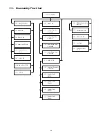
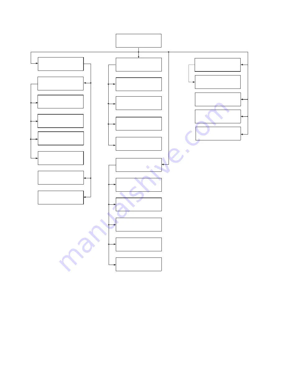
11.1. Disassembly Flow Chart
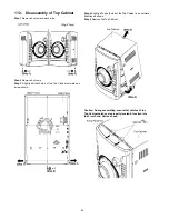
11.3 . Top Cabinet
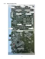
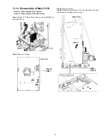
11.12. Main P. C.B.
11.23. CD Mechanism Unit
(BRS11C )
11.26. Rear Panel
CD Servo P. C.B.
11.25
CD Interface P.C.B.
11.24.
11.27. Voltage Selector
P. C.B.
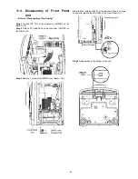
11.4 . Front panel Unit
11.6 .
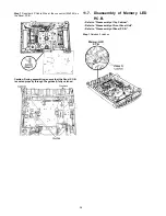
Memory LED P.C.B.
11.7 .
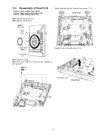
Panel P. C.B.
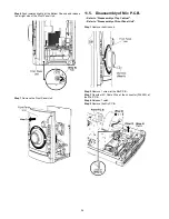
11.5 . MIC P.C.B.
11.8 . Remote Sensor
P. C.B.
11.9 . USB P. C.B.
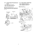
11.10. Music Port P. C.B.
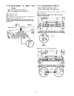
11.11. CD Lid
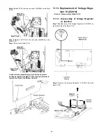
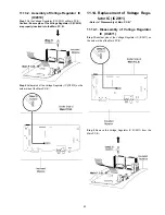
11.13. Voltage Regulator
IC (IC2010)
11.14. Voltage Regulator
IC (IC2011)
11.15. Audio Digital Amp
Amp
IC (IC5800)
11.16. Audio Digital
IC (IC5700)
11.17. SMPS P. C.B.
11.18. Switching Regulator
IC (IC5701 )
11.19. Rectifier Diode
(D5702)
11.20. Rectifier Diode
(D5801)
11.21. Rectifier Diode
(D5802)
11.22. Rectifier Diode
(D5803)
Содержание SA-AKX54PH
Страница 13: ...13 5 General Introduction 5 1 Media Information ...
Страница 14: ...14 6 Location of Controls and Components 6 1 Remote Control Key Button Operation ...
Страница 15: ...15 6 2 Main Unit Key Button Operation ...
Страница 16: ...16 7 Installation Instructions 7 1 Speaker and A C Connection ...
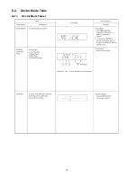
Страница 18: ...18 8 2 Doctor Mode Table 8 2 1 Doctor Mode Table 1 ...
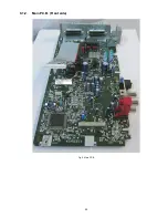
Страница 25: ...25 9 1 2 Main P C B Front side Fig 2 Main P C B ...
Страница 28: ...28 9 3 D Amp IC Operation Control ...
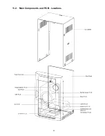
Страница 33: ...33 11 2 Main Components and P C B Locations ...
Страница 66: ...66 ...
Страница 76: ...76 ...
Страница 78: ...78 ...
Страница 120: ...120 ...

