background image

4

1.2.

Before Use (For PH only)

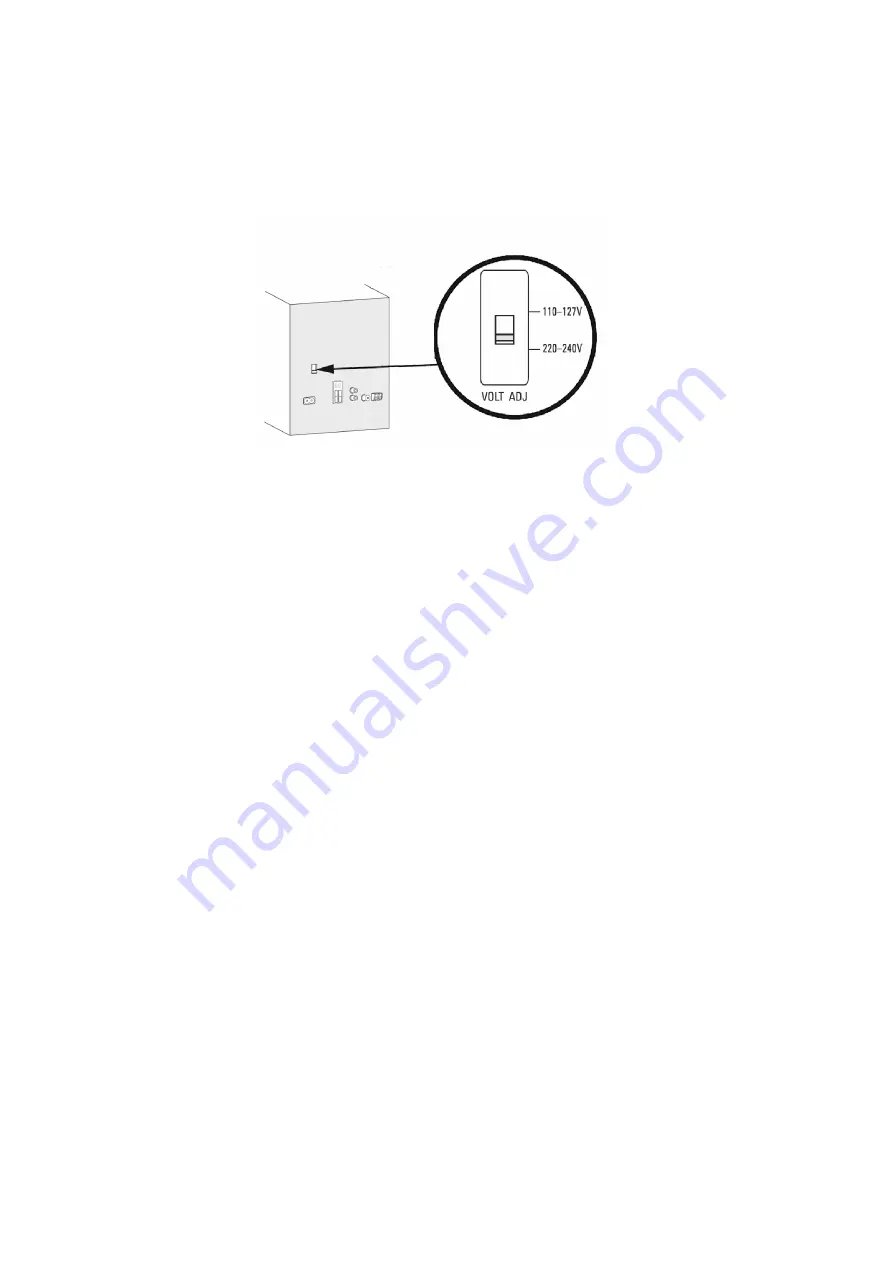
Be sure to disconnect the mains cord before adjusting the voltage selector as shown in Figure 1-2.
Use a minus(-) screwdriver to set the voltage selector (on the rear panel) to the voltage setting for the area in which the unit will be
used.
Note that this unit will be seriously damaged if this setting is not made correctly. (There is no voltage selector for some countries,
the correct voltage is already set.)

Figure 1-2

1.3.

Before Repair and Adjustment

Caution:

DO NOT SHORT-CIRCUIT DIRECTLY (with a screwdriver blade, for instance), as this may destroy solid state devices.

After repairs are completed, restore power gradually using a variac to avoid overcurrent.
Current consumption at AC 110~127 V / 220~240 V, 50/60 Hz in Power ON, FM Tuner at volume minimal mode should be ~ 250
mA (PH).
Current consumption at AC 120 V, 60 Hz in Power ON, FM Tuner at volume minimal mode should be ~ 250 mA (PN).

1.4.

Protection Circuitry

The protection circuitry may have operated if either of the following conditions are noticed:

• No sound is heard when the power is turned on.
• Sound stops during a performance.

The function of this circuitry is to prevent circuitry damage if, for example, the positive and negative speaker connection wires are
“shorted”, or if speaker systems with an impedance less than the indicated rated impedance of the amplifier are used.
If this occurs, follow the procedure outlines below:

1. Turn off the power.
2. Determine the cause of the problem and correct it.
3. Turn on the power once again after one minute.

Note:
When the protection circuitry functions, the unit will not operate unless the power is first turned off and then on again.

Содержание SA-AKX18PH

Страница 1: ...s 7 2 2 Precaution of Laser Diode 7 2 3 General description about Lead Free Solder PbF 8 2 4 Handling Precautions for Traverse Unit 8 2 5 Grounding for electrostatic breakdown prevention 9 3 Service Navigation 10 3 1 Service Information 10 4 Specifications 11 5 Location of Controls and Components 12 5 1 Remote Control Key Button Operation 12 5 2 Main Unit Key Button Operation 12 6 Service Mode 13 ...

Страница 2: ... 11 Disassembly of CD Mechanism Unit 27 8 12 Disassembly of CD Interface P C B 28 9 Service Position 29 9 1 Checking of Panel P C B and LCD P C B 29 9 2 Checking and Repairing of Main P C B and SMPS P C B 29 10 Block Diagram 31 10 1 System Control 31 10 2 Audio 33 10 3 Power Supply 34 11 Wiring Connection Diagram 35 12 Schematic Diagram 37 12 1 Schematic Diagram Notes 37 12 2 MAIN Damp Tuner AUX U...

Страница 3: ...shock hazards 1 1 1 Leakage Current Cold Check 1 Unplug the AC cord and connect a jumper between the two prongs on the plug 2 Measure the resistance value with an ohmmeter between the jumpered AC plug and each exposed metallic cabinet part on the equipment such as screwheads connectors control shafts etc When the exposed metallic part has a return path to the chassis the reading should be between ...

Страница 4: ...240 V 50 60 Hz in Power ON FM Tuner at volume minimal mode should be 250 mA PH Current consumption at AC 120 V 60 Hz in Power ON FM Tuner at volume minimal mode should be 250 mA PN 1 4 Protection Circuitry The protection circuitry may have operated if either of the following conditions are noticed No sound is heard when the power is turned on Sound stops during a performance The function of this c...

Страница 5: ... Supply SMPS to provide the power supply to the unit Here is the supplied part no for the SMPS Module 1 N0AB2GK00001 For PN 2 N0AD2GK00001 For PH Disconnect AC power to discharge the AC Capacitors C1 PH C2 through a 10 10 W resistor to ground 1 5 1 For PN 1 5 2 For PH ...

Страница 6: ...be replaced with manufacturer s specified parts to prevent shock fire or other hazards Do not modify the original design without permission of manufacturer Safety Ref No Part No Part Name Description Remarks 13 RGR0443M A1A REAR APNEL PN 13 RGR0443N A2A REAR PANEL PH 26 RKM07132 K1 TOP CABINET 301 RAE1044Z V TRAVERSE UNIT A2 K2CB2CB00022 AC CORD PN A2 K2CQ2YY00119 AC CORD PH A3 RQT9894 M O I BOOK ...

Страница 7: ...ent to damage ES devices 6 Do not remove a replacement ES device from its protective package until immediately before you are ready to install it Most replacement ES devices are packaged with leads electrically shorted together by conductive foam aluminum foil or compara ble conductive material 7 Immediately before removing the protective material from the leads of a replacement ES device touch th...

Страница 8: ...e Parts Route The following 3 types of lead free solder are available through the service parts route RFKZ03D01K 0 3mm 100g Reel RFKZ06D01K 0 6mm 100g Reel RFKZ10D01K 1 0mm 100g Reel Note Ingredient tin Sn 96 5 silver Ag 3 0 Copper Cu 0 5 Cobalt Co Germanium Ge 0 1 to 0 3 2 4 Handling Precautions for Traverse Unit The laser diode in the optical pickup unit may break down due to static electricity ...

Страница 9: ...by the static electricity of the working environ ment Repair in the working environment that is grounded 2 5 1 Worktable grounding Put a conductive material sheet or iron sheet on the area where the optical pickup is placed and ground the sheet 2 5 2 Human body grounding Use the anti static wrist strap to discharge the static electricity form your body Figure 2 3 Figure 2 3 ...

Страница 10: ...he drawing reference numbers If the circuit is changed or modified this information will be followed by supplement service manual to be filed with original service manual 3 1 1 Firmware Update Procedure Start Write encrypted UPD bin to CD R Turn On main set Insert CD R with UPD bin and close TOC reading Writing starts 0 20 40 60 80 100 CHECKING GOOD display 3 sec Set auto turn Off Cold Start End O...

Страница 11: ...stance 10 m line of sight USB section USB Port USB standard USB 2 0 full speed Media file format support MP3 mp3 USB device file system FAT12 FAT16 FAT32 USB port power 500 mA max USB recording Bit rate 128 kbps USB recording speed 1x 3x CD only Recording file format MP3 mp3 General Power supply AC 110 to 127 220 to 240 V 50 60 Hz for PH AC 120 V 60 Hz for PN Power consumption 50 W Dimensions W x ...

Страница 12: ...12 5 Location of Controls and Components 5 1 Remote Control Key Button Operation 5 2 Main Unit Key Button Operation ...

Страница 13: ... into the Sales demonstration lock mode Step 1 Turn on the unit Step 2 Select to any mode function Step 3 Press and hold OPEN CLOSE and CD keys for 5 sec or more The display will show upon entering into this mode for 2 sec Note OPEN CLOSE button is invalid and the main unit displays LOCKED while the lock function mode is entered 6 2 2 Cancellation of Sales demonstration lock mode Step 1 Turn on th...

Страница 14: ...rol In CD mode 1 Enter into Doctor Mode 2 To exit press DELETE button on remote control or press POWER I button on Main Unit Displaying of 1 Year Develop 2 Model Type 3 ROM Type 4 Firmware Version Display 1 Display 2 Checksum Hex Cold Start To active cold start upon next AC power up when reset start is execute the next time In Doctor Mode 1 Press SLEEP button on the remote control Version No 001 9...

Страница 15: ...n reach 99999999 will change to 00000000 Cancellation Display Traverse Test To determine the traverse unit operation for inner outer access track The counter will increment by one When reach 99999999 will change to 00000000 The counter will increment by one When reach 99999999 will change to 00000000 Cancellation Display Reliability Test Combination In this mode ensure the CD is in the main unit T...

Страница 16: ...rol Display of auto adjustment result Reference table ERROR Code Status Condition 0 1 2 4 6 8 A C E F AOC1 AOC2 O O O O O O O O ABC2 ABC1 O X O X O X O X 2ndAOC1 O O X X O O X X FAGC TAGC O O O O X X X X AGC2 O O O O O O O O O OK X NG In case that time out happens Either one of FO AOC TR AOC and FO coarse AGC is NG If the AGC is NG ignore others To cancel this mode press 0 button on the remote con...

Страница 17: ...for 2 seconds Error Code Information System will perform a check on any unusual error code from the memory Example Step 1 In self diagnostic mode Press g on main unit To exit press 8 on main unit or remote control Delete error code To clear the stored in memory EEPROM IC Step 1 In self diagnostic mode Press 0 on remote control Error Code Diagnostic Contents Description of error Automatic FL Displa...

Страница 18: ...ntrol to Turn ON the Unit Press PAIRING on the Set or Remote Control Display BLUETOOTH Check Main PCB NG PAIRING will display and blinking while handphone or other devices are Connecting to the Set Do the Cold Start AC Plug out Press and Hold Power Button then AC Plug IN wait to display then will OFF the Set back to start NG Check Main PCB NG option 1 option 2 The set will displayed the READY foll...

Страница 19: ...on of Unit or Remote Control to Turn ON the Unit Check Main PCB NG Press Play FL Display Track Count NG Output Sound No Problem Found OK OK CD Mode OK Check CD Mechanism Press Power Button of Unit or Remote Control to Turn ON the Unit Check Main PCB NG Insert USB Thumdrive FL Display USB A B Press Play NG Output Sound No Problem Found OK USB Mode OK OK Change USB Device Press Power Button of Unit ...

Страница 20: ...ule SMPS Module Fuse F1 0 ohm 2 2 Pri Cap C2 300V or more 3 3 Sec Cap C17 1 1 13V or 33V Main PCB Main PCB 4 5 C1008 C1009 6V IC1005_Pin 2 3 3V 6 IC1004_Pin 3 1 6V 7 CN2500_Pin 1 3 5V 3 3V 12V 8 CN2503 Pin 6 USB A Pin 7 USB B 5V ...

Страница 21: ...ching heatsinks due to its high temperature after prolong use Be sure to use proper service tools equipments or jigs during repair Select items from the following indexes when disassembly or replacement are required Disassembly of Top Cabinet Disassembly of Front Panel Unit Disassembly of Panel P C B and LCD P C B Disassembly of USB P C B Disassembly of Rear Panel Disassembly of Main P C B Disasse...

Страница 22: ...22 8 3 Main Components and P C B Locations ...

Страница 23: ...utwards as arrow shown Step 4 Slightly lift up to remove Top Cabinet 8 5 Disassembly of Front Panel Unit Refer to Disassembly of Top Cabinet Step 1 Detach 8P Cable Wire at the connector CN2502 on Main P C B Step 2 Detach 17P FFC at the connector CN2500 on Main P C B Step 3 Release tabs on both side of the Front Panel Unit ...

Страница 24: ...tach to remove Front Panel Unit 8 6 Disassembly of Panel P C B and LCD P C B Refer to Disassembly of Top Cabinet Refer to Disassembly of Front Panel Unit Step 1 Remove Volume Knob Step 2 Remove Control Knob Step 3 Remove 7 screws Step 4 Release catches ...

Страница 25: ... Top Cabinet Refer to Disassembly of Front Panel Unit Refer to Disassembly of Panel P C B and LCD P C B Step 1 Remove 1 screw Step 2 Remove catches Step 3 Remove USB P C B 8 8 Disassembly of Rear Panel Refer to Disassembly of Top Cabinet Step 1 Remove 9 screws Step 2 Detach Voltage Selector P C B ...

Страница 26: ...bly of Top Cabinet Refer to Disassembly of Rear Panel Step 1 Detach 10P Cable Wire at the connector CON2 on SMPS P C B Step 2 Detach 24P FFC at the connector P2005 on Main P C B Step 3 Detach 10P FFC at the connector P2004 on Main P C B Step 4 Detach 17P FFC at the connector CN2500 on Main P C B Step 5 Detach 8P Cable at the connector CN2502 on Main P C B Step 6 Remove 2 screws Step 7 Remove Main ...

Страница 27: ... screws Step 3 Release catch Step 4 Remove SMPS Module and Voltage Selector P C B 8 11 Disassembly of CD Mecha nism Unit Refer to Disassembly of Top Cabinet Refer to Disassembly of Front Panel Unit Step 1 Remove 8 screws Step 2 Detach Voltage Selector P C B Step 3 Detach 10P FFC at a connector P2004 on Main P C B Step 4 Detach 24P FFC at a connector P2005 on Main P C B Step 5 Remove 1 screw Step 6...

Страница 28: ...hanism Unit 8 12 Disassembly of CD Interface P C B Refer to Disassembly of Top Cabinet Refer to Disassembly of Front Panel Unit Refer to Disassembly of CD Mechanism Unit Step 1 Remove 2 screws Step 2 Desolder pins of the motor M7301 Step 3 Desolder pins of the motor M7302 Step 4 Remove CD Interface P C B ...

Страница 29: ...am shown 9 2 Checking and Repairing of Main P C B and SMPS P C B Step 1 Remove Top Cabinet Step 2 Remove Front Panel Unit Step 3 Remove Rear Panel Step 4 Remove Main P C B Step 5 Remove SMPS Module and Voltage Selector P C B Step 6 Positioned the Main P C B SMPS Module and the Volt age Selector P C B on the insulated material Step 7 Attach 10P Cable at a connector CON2 on the SMPS Module Step 8 At...

Страница 30: ...30 ...

Страница 31: ... ZJ9001 LED DIMMER LED DIMMER 3 WR 1 CS DP900 LCD 5V Q900 LED DRIVE Q2002 SWITCH LCD P C B COM0 COM3 SEG0 SEG31 D993 9 9 CN9000 CN2500 3 3V REMOTE SENSOR IR9000 RMT RMT SOC C1AB00004188 IC2001 MAIN P C B NOTE REF IS FOR INDICATION ONLY REM IN 120 AC 50 BD 51 E 54 F 55 MD 56 LDO 57 TRDRV 62 SPDRV 64 TRVDRV 63 INNER SW 31 OPEN SW 29 CLOSE SW 30 LD CCW 6 LD CW 5 FODRV 61 5 6 CN7002 P2004 OPEN SW 8 3 ...

Страница 32: ...00 SWITCH QR2500 LED DRIVE QR2002 SWITCH 5V USB REC LED 14 FAN OUT2 15 USB SEL 2 USB MUX OE 13 USB D 97 USB D 98 PW D5V 8 8 CN2502 ZJ9301 PW D5V D9300 PROTECT PROTECT SYNC SYNC 37 SMPS ID SMPS ID 1 NRST NRST DC DET PWR DC DET PWR 9 BT PCONT BT PCONT BT PCONT 4 USB B USB B USB B 10 USB A USB A USB A 25 PCONT1 PCONT1 PCONT1 POWER 26 PCONT2 PCONT2 PCONT2 PCONT SMPS ID NRST 94 USB OVC USB OVC USB OVC ...

Страница 33: ...T090 IC6500 MAIN P C B 32V Q6007 Q6300 DC DETECT CIRCUIT Q6001 Q6002 SPEAKERS OUT D 27 OUT D 28 OUT C 32 BST D 23 BST C 24 OUT A 40 OUT A 39 OUT B 35 BST A 44 BST B 43 4 JK6000 3 JK6000 RIGHT LEFT 1 JK6000 2 JK6000 POWER AMPLIFIER C1AB00003994 IC6000 6 INPUT B PWM1B 27 5 INPUT A PWM1A 28 14 INPUT C PWM2A 30 15 INPUT D PWM2B 29 DOUT FM ANT JK51 FM AM RADIO RECEIVER VUEALLPT087 IC52 LIN 15 RIN 16 GC...

Страница 34: ... SOC 1R5V 9 ZJ1002 SYNC 7 ZJ1002 SMPS ID 8 ZJ1002 TEMP DET SWITCHING MODE POWER SUPPLY CIRCUIT AC INLET SMPS MODULE DC DET PWR DC DET PWR 6 6 ZJ9301 CN2502 5V USB P C B LCD P C B PANEL P C B PW USBA 5V PW USBA 5V 7 7 ZJ9301 CN2502 5V PW USBB 5V PW USBA 5V PW USBB 5V 5V PW 5V 3 3V PW 3R3V PW USBB 5V 14 4 CN9000 CN2500 3 3V PW SYS 3R3V PW SYS 3R3V PW SYS 3R3V 17 1 CN9000 CN2500 1 1 ZJ6000 ZJ9001 PW ...

Страница 35: ...TION ONLY TO CD LOADING P C B CD MECHANISM UNIT CN7002 CN7001 10P 5P TO OPTICAL PICKUP UNIT CD MECHANISM UNIT TO SMPS MODULE P C B CN2502 P2005 P2004 CN1000 ZJ9301 ZJ6000 ZJ9001 CN9000 8P CN2500 17P 10P 8P 7P 7P 17P 10P 24P MAIN P C B A PANEL P C B B LCD P C B C USB P C B D CD INTERFACE P C B E ...

Страница 36: ...36 ...

Страница 37: ...0 000 Capacitor Unit of capacitance is F unless otherwise noted F Far ads pF pico Farad Coil Unit of inductance is H unless otherwise noted REF IS FOR INDICATION ONLY Voltage and signal line S7201 Reset switch S9001 Power switch S9002 Open Close switch S9003 Tune Mode Stop switch S9004 DJ Jukebox switch S9005 Latin Preset EQ switch S9006 MANUAL EQ switch S9007 D BASS switch S9008 USB REC PAUSE swi...

Страница 38: ...38 ...

Страница 39: ...ROTECTION SWITCH Q6300 B1ABCF000011 SPEAKER PROTECTION SWITCH Q6007 B1ABCF000011 47K R6055 C6027 0 1 R6057 220K B1ADGD000019 Q6002 0 1 C6036 1 C6039 1 C6031 0 1 C6032 50V1000 C6033 C6022 10 R6011 G1C4R7MA0172 L6006 10K R6072 1 C6047 1 C6048 100K R6067 100K R6069 100K R6066 100K R6068 0 01 C6063 0 01 C6064 3 3 R6061 3 3 R6062 0 1 1 1 C6023 0 1 C6021 0 1 C6018 10 C6005 0 1 C6019 22K R6046 10 R6007 1...

Страница 40: ...7 10K 4 7K R6134 10K R6146 C6099 680P 680P C6100 1 3 4 2 JK6002 4 7K R6133 J0JBC0000118 LB53 C62 0 1 R56 220 R57 1K 2 2K R60 C67 3P C51 1000P LB51 J0JYC0000656 L51 G1CR18JA0020 LB52 0 VA51 EZAEG2A50AX G2 G3 G1 JK51 L53 0 0 47 C52 4 7K R54 R53 4 7K 1 2 JK52 0 1 C61 4 12 1 2 14 T1 17 19 18 16 15 20 3 13 THERMAL PAD 5 11 10 8 9 7 6 IC52 4 G2 G1 6 2 3 1 G2A380Y00002 L52 R52 560 R51 2 2K R55 220 DSP_SC...

Страница 41: ...R3V LED_DIMMER 0 01 C2527 470P C2532 0 01 C2533 470P C2531 0 01 C2535 0 01 C2537 0 01 C2536 0 01 C2534 0 01 C2528 470P C2530 470P C2529 0 01 C2526 KEY1 RMT VOL_JOG ROT_JOG NC NC 6 5 8 9 11 12 10 15 17 17 16 13 14 7 2 1 1 4 3 CN2500 100 R2501 B1GBCFGN0016 LED DRIVE QR2500 330 R2503 DSA200100L SWITCH Q2500 R2510 100K 3 1 2 4 5 C0DBZYY00716 HIGH SIDE SWITCH IC2502 R2504 10K 0 1 C2506 C2507 4 7 0 1 C2...

Страница 42: ...527 10K 1 R6541 R6532 R6531 10K 10K 10K 10K R6587 10K C6591 C6500 10K 4 5 T1 44 45 46 47 48 2 1 3 32 34 36 35 33 40 41 42 43 37 38 39 8 16 17 15 14 13 9 6 7 27 25 22 23 20 19 21 24 26 18 30 31 28 29 THERMAL PAD 11 12 10 IC6500 VUEALLPT090 DSP C6521 1 16V47 0 47 R6559 100 C6501 C6523 16V22 1 DSP_RESET DSP_SCL DSP_MUTE DSP_SDA DGND MI MI MI MI TU TU MI MI MI MI DA TU PW_3R3V I2S_WCK I2S_BCK BCK PWM1...

Страница 43: ...8 390 C1023 0 1 3 1 2 B0ADDJ000032 D1002 B1AAKD000012 12V VOLTAGE REGULATOR Q1000 0 1 C1047 C1000 10 7 5K R1004 10K R1006 R1068 47 56K R1005 C1001 10 2 1 3 IC1000 C0DBGYY03909 3 3V VOLTAGE CONVERTER DC_DET_PWR PW_12V PW_SYS_3R3V PW_SOC_1R5V MI MI MI MI BT DA MI MI US US MI PW_BT_5V PROTECT PW_32V PCONT1 PCONT2 MI MI MI MI MI DA SMPS_ID DGND SYNC PW_3R3V PW_6V PW_USB5V PW_5V 1 4 2 3 IC1004 C0DBGYY0...

Страница 44: ... J0JCC0000309 R2021 0 R2110 2 2K 127 125 123 117 116 118 115 120 121 119 98 97 99 105 104 106 102 100 101 103 113 111 109 108 110 112 114 107 122 124 126 63 50 52 51 45 47 46 41 42 38 34 36 37 35 40 39 44 43 49 48 60 62 61 56 57 53 55 54 59 58 64 95 92 93 88 89 84 85 80 81 72 67 65 66 71 69 68 70 76 78 79 77 73 75 74 83 82 87 86 91 90 94 96 9 10 7 8 12 15 16 13 14 11 1 4 2 3 6 5 128 31 29 23 26 27...

Страница 45: ... LDM TRV TRV R2176 J0JCC0000309 SPM SPM LDM R2177 J0JCC0000309 R2175 J0JCC0000309 R2174 J0JCC0000309 R2173 J0JCC0000309 C2166 0 01 C2167 0 01 C2162 10 J0JBC0000134 LB2010 R2178 J0JCC0000309 F F R2181 J0JCC0000309 R2179 J0JCC0000309 T T R2180 J0JCC0000309 C2171 0 01 10 C2170 LB2011 G1C100KA0101 10 C2164 C2165 0 1 0 01 C2163 6 7 5 9 13 15 14 11 10 12 21 22 18 16 17 20 19 8 1 3 4 2 24 23 P2005 0 R217...

Страница 46: ...00301 R2020 J0JCC0000301 R2019 J0JCC0000301 R2016 J0JCC0000301 R2015 J0JCC0000301 R2017 J0JCC0000301 C2122 10 LB2006 0 D2001 DA2J10100L R2117 R2093 560K R2089 CR_TIMER FAN_OUT2 C2121 0 1 2 1 7 8 5 4 3 6 IC2003 RFKWFAKX18LM 16MB FLASH MEMORY PW_3R3V LB2016 J0JBC0000010 PW_SYS_3R3V VO VO TU DA DA DS PW_SYS_3R3V DGND 6 8K R2338 R2115 2 7K 2 7K R2330 0 4 7K 100 R2340 C2148 10 B1GBCFJJ0051 SWITCH QR200...

Страница 47: ..._5V LCD_DATA PW_5V LED_DIMMER PW_3V3 LCD_CE LCD_WR 22K R9023 6 5 8 9 11 12 10 14 15 13 7 2 1 1 4 3 17 17 16 CN9000 C9001 100P R9022 12K ROT_JOG VOL_JOG C9000 100P R9011 2 7K S9015 S9013 S9012 S9014 R9014 18K R9012 3 9K R9013 7 5K S9011 RMT 4 5 1 3 2 7 6 ZJ9001 100P C9004 VR9000 C9005 1000P LCD_CE LCD_WR DGND VOLUME PW_5V ALBUM TRACK FL_DAT PW_3V3 LED_DIMMER NC NC NC BT PAIRING RADIO AUX USB CD PLA...

Страница 48: ...29 SEG28 SEG30 SEG27 SEG22 SEG12 SEG13 SEG11 SEG16 SEG18 SEG17 SEG15 SEG21 SEG19 SEG20 SEG14 21 5 6 3 1 2 4 19 9 7 8 16 17 11 10 12 15 14 13 18 20 35 37 38 42 44 43 39 40 41 36 33 22 31 29 27 24 23 26 25 28 30 32 34 IC900 C0HBA0000295 LED DRIVER COM2 SEG3 SEG5 SEG6 SEG4 COM3 SEG0 SEG2 SEG1 SEG13 SEG15 SEG14 SEG9 SEG7 SEG8 SEG11 SEG12 SEG10 SEG18 SEG24 SEG22 SEG23 SEG28 SEG27 SEG31 SEG30 SEG29 SEG2...

Страница 49: ...A AKX18PH PN MAIN CD INTERFACE P C B A MAIN P C B REP5061B PH REP5061A PN SIDE A E CD INTERFACE P C B REP4945A PbF TP2501 TP2500 3760A 3760A M7301 TRAVERSE MOTOR SPINDLE MOTOR M7302 CN7001 S7201 RESET TO LOADING P C B CD MECHANISM UNIT BRS12C CN7002 3556A PbF 3556A 2 4 3 1 1 2 3 4 5 6 9 10 7 8 1 2 1 2 3 4 5 1 2 ...

Страница 50: ...27 R1026 C1004 L1001 D1000 R1030 C1003 IC1002 C1005 C6109 R2063 R2422 R2065 D1006 D1007 C6108 R60 R56 C61 C62 C67 IC52 JK51 JK52 LB52 L52 L53 R51 R52 R53 R54 R55 R57 R59 VA51 JK6002 R6146 C6099 R6147 C6100 R6134 R6136 R6135 R6133 C66 C52 LB51 C51 L51 L6006 Q6001 Q6002 R6054 R6055 R6056 R6057 C6027 R6070 R6132 C6068 Q6007 Q6300 C6500 C6521 C6592 C6591 R6559 LB6501 R6542 R6541 R6532 R6531 R6511 R651...

Страница 51: ...R9022 R9023 R9001 R9009 R9011 R9012 R9014 W100 W106 W105 W104 W103 W102 W101 1 11 12 22 23 33 34 44 DP900 D993 ZJ6000 D9301 D9300 JK9300 JK9301 ZJ9301 S9001 S9003 S9005 S9007 S9009 S9011 S9013 S9008 S9006 S9004 S9002 CN9000 ZJ9001 IR9000 VR9001 S9010 S9015 S9012 S9014 VOLUME SENSOR USB PORT B USB PORT A CONTROL VR9000 ALBUM TRACK BT PAIRING PLAY PAUSE TUNE MODE STOP RADIO AUX OPEN CLOSE POWER DJ J...

Страница 52: ...52 ...

Страница 53: ... MODE 1 2 3 4 5 6 7 8 9 10 CD PLAY 12 13 4 2 9 2 4 0 5 2 6 0 8 0 8 0 5 9 STANDBY 12 13 4 2 9 2 4 0 5 2 6 0 8 0 8 0 5 9 REF NO MODE 1 2 3 4 CD PLAY 3 2 0 1 6 3 2 STANDBY 3 2 0 1 6 3 2 REF NO MODE 1 2 3 CD PLAY 0 3 2 4 2 STANDBY 0 3 2 4 2 REF NO MODE 1 2 3 4 5 6 7 8 9 10 11 12 13 14 15 16 17 18 19 20 CD PLAY 3 2 3 2 3 2 3 2 3 1 3 2 0 0 0 1 1 3 2 0 0 0 0 0 3 2 1 6 0 0 STANDBY 3 2 3 2 3 2 3 2 0 0 0 0 ...

Страница 54: ... 2 6 0 0 5 9 0 0 3 1 2 9 2 9 3 1 3 3 1 3 6 2 5 5 9 2 4 STANDBY 1 6 5 9 2 6 1 6 2 6 0 0 5 9 0 0 3 3 3 3 3 3 3 3 5 9 2 4 REF NO MODE 21 22 23 24 25 26 27 28 29 30 CD PLAY 1 5 0 1 8 5 9 5 9 1 6 1 6 3 3 0 0 STANDBY 1 5 0 1 6 5 9 5 9 1 6 1 6 3 3 0 0 REF NO MODE 1 2 3 4 CD PLAY 3 2 3 2 0 0 STANDBY 3 2 3 2 0 0 REF NO MODE 1 2 3 4 5 6 7 8 9 10 CD PLAY 1 6 1 5 1 5 0 1 5 1 5 1 5 0 3 3 3 2 STANDBY 1 5 1 5 1 ...

Страница 55: ...0 1 5 3 3 0 3 3 1 7 1 7 1 7 1 7 1 7 1 7 1 7 1 7 3 3 0 0 0 0 3 3 REF NO MODE 41 42 43 44 45 46 47 48 CD PLAY 1 4 1 5 0 0 3 3 0 0 0 STANDBY 1 4 1 5 0 0 0 0 0 0 REF NO MODE 1 2 3 4 5 6 7 8 9 10 11 12 13 14 15 16 CD PLAY 0 3 2 0 3 2 0 0 0 0 4 6 0 0 0 3 2 0 0 0 STANDBY 0 3 2 0 3 2 0 0 0 0 4 6 0 0 0 3 2 0 0 0 REF NO MODE 1 2 3 4 CD PLAY 3 1 0 4 6 5 STANDBY 3 1 0 4 6 5 REF NO MODE E C B E C B E C B E C B...

Страница 56: ... 5 1 5 1 5 1 5 1 5 1 5 1 5 1 5 1 5 1 5 1 5 1 5 STANDBY 1 5 1 5 1 5 1 5 1 5 1 5 1 5 1 5 1 5 1 5 1 5 1 5 1 5 1 5 1 5 1 5 1 5 1 5 1 5 1 5 REF NO MODE 41 42 43 44 CD PLAY 1 5 1 5 1 5 1 5 STANDBY 1 5 1 5 1 5 1 5 REF NO MODE E C B CD PLAY 0 0 1 3 2 STANDBY 0 0 1 3 2 SA AKX18PH PN LCD P C B Q900 IC900 IC900 IC900 WF No IC2001 124 PLAY 2 1Vp p 10msec div WF No IC2001 125 PLAY 3 4Vp p 20usec div WF No IC60...

Страница 57: ...PANEL P C B LCD P C B VR9001 VR9000 ZJ9301 ZJ9001 ZJ6000 JK9301 JK9300 IR9000 DP900 CN9000 42 41 36 35 31 30 28 27 26 25 25 23 23 23 23 23 21 21 21 21 20 20 20 20 20 20 20 20 18 17 14 12 12 11 11 8 7 6 3 2 a b c c 1 2 3 4 5 6 7 8 9 A B C D E F G H 10 11 12 13 NOTE PART IS NOT SUPPLIED REF IS FOR INDICATION ONLY SA AKX18PH PN K CABINET DRAWINGS ...

Страница 58: ... D AMP HEATSINK UNIT CN7002 CN7001 CN2502 CN2500 40 39 312 312 301 38 38 37 37 34 33 32 29 29 25 25 24 24 23 23 23 23 23 23 23 23 23 22 22 22 22 22 22 22 22 22 22 19 19 13 5 4 1 a b d d e e f f g g h h i i 1 2 3 4 5 6 7 8 9 A B C D E F G H 10 11 12 13 NOTE PART IS NOT SUPPLIED REF IS FOR INDICATION ONLY SA AKX18PH PN K CABINET DRAWINGS ...

Страница 59: ... PLUG ADAPTOR FOR PH ONLY A6 AM LOOP ANTENNA A5 FM INDOOR ANTENNA A4 A3 OI BOOK AC CORD FOR PN ONLY AC CORD FOR PH ONLY A2 A2 A1 1 A1 P3 P2 P2 FRONT P1 SC AKX18PH PN K PACKAGING DRAWINGS POLYFOAM TOP POLYFOAM BOTTOM P2 1 2 3 4 5 6 7 8 9 A B C D E F G H 10 11 12 13 ...

Страница 60: ...60 ...

Страница 61: ...46 L SCREW 8 21 RHD30007 K2J SCREW 4 22 RHD30111 31 SCREW 10 23 RHD30119 S SCREW 13 PN 23 RHD30119 S SCREW 14 PH 24 RHDX031008 SCREW 2 25 RKAX0042 K LEG CUSHION 4 26 RKM0713 K1 TOP CABINET 1 27 RKW1027 Q CENTER ORNAMENT 1 28 RKW1063 Q FL WINDOW 1 29 RMA2442 CHASSIS SUPPORT 2 30 RMB0930 CD LID SPRING 1 31 RMGX0033A K CD LID CUSHION 1 32 RMK0837 1 INNER CHASSIS 1 33 RMKX1031A 1 BOTTOM CHASSIS 1 34 R...

Страница 62: ...T 1 ACCESSORIES A1 N2QAYB000944 REMOTE CONTROL 1 A1 1 RKK AKX18PHK R C BATTERY COVER 1 A2 K2CB2CB00022 AC CORD 1 PN A2 K2CQ2YY00119 AC CORD 1 PH A3 RQT9894 1M O I BOOK En Sp 1 A4 RSAX0002 FM INDOOR ANTENNA 1 A5 N1DYYYY00011 AM LOOP ANTENNA 1 A6 K2DAYYY00002 AC PLUG ADAPTOR 1 PH Safety Ref No Part No Part Name Description Qty Remarks ...

Страница 63: ... C0DBZYY00716 IC 1 E S D IC2502 C0DBZYY00716 IC 1 E S D IC6000 C1AB00003994 IC 1 E S D IC6500 VUEALLPT090 IC 1 E S D IC7001 C0DBGYY00969 IC 1 E S D TRANSISTORS Q900 B1GBCFJN0033 TRANSISTOR 1 E S D Q1000 B1AAKD000012 TRANSISTOR 1 E S D Q2001 B1ADCF000001 TRANSISTOR 1 E S D Q2002 B1ABCF000011 TRANSISTOR 1 E S D Q2500 DSA200100L TRANSISTOR 1 E S D Q6001 B1ABCF000011 TRANSISTOR 1 E S D Q6002 B1ADGD000...

Страница 64: ...00 J0JBC0000010 INDUCTOR 1 LB6501 J0JBC0000010 INDUCTOR 1 Safety Ref No Part No Part Name Description Qty Remarks LB9300 J0JHC0000118 INDUCTOR 1 LB9301 J0JHC0000118 INDUCTOR 1 R2004 J0JCC0000309 INDUCTOR 1 R2005 J0JCC0000309 INDUCTOR 1 R2006 J0JCC0000309 INDUCTOR 1 R2013 J0JCC0000309 INDUCTOR 1 R2014 J0JCC0000309 INDUCTOR 1 R2015 J0JCC0000301 INDUCTOR 1 R2016 J0JCC0000301 INDUCTOR 1 R2017 J0JCC000...

Страница 65: ...69 D0GBR00J0004 0 1 10W 1 R1070 D0GB222JA065 2 2K 1 10W 1 R2001 D0GB103JA065 10K 1 10W 1 R2002 D0GB334JA065 330K 1 10W 1 R2012 D0GB471JA065 470 1 10W 1 R2021 D0GBR00J0004 0 1 10W 1 R2026 D0GB102JA065 1K 1 10W 1 R2035 D0GB101JA065 100 1 10W 1 R2036 D0GB105JA065 1M 1 10W 1 R2037 D0GB104JA065 100K 1 10W 1 R2038 D0GB106JA065 10M 1 10W 1 R2050 D0GBR00J0004 0 1 10W 1 R2051 D0GBR00J0004 0 1 10W 1 R2052 D...

Страница 66: ...065 10K 1 10W 1 R6532 D0GB103JA065 10K 1 10W 1 R6541 D0GB103JA065 10K 1 10W 1 Safety Ref No Part No Part Name Description Qty Remarks R6542 D0GB103JA065 10K 1 10W 1 R6550 D0GB221JA065 220 1 10W 1 R6551 D0GB221JA065 220 1 10W 1 R6552 D0GBR00J0004 0 1 10W 1 R6553 D0GBR00J0004 0 1 10W 1 R6554 D0GB101JA065 100 1 10W 1 R6556 D0GB101JA065 100 1 10W 1 R6557 D0GB101JA065 100 1 10W 1 R6559 D0GB101JA065 100...

Страница 67: ...uF 50V 1 C2526 F1G1H103A835 0 01uF 50V 1 C2527 F1G1H103A835 0 01uF 50V 1 C2528 F1G1H103A835 0 01uF 50V 1 C2529 F1G1H471A830 470pF 50V 1 Safety Ref No Part No Part Name Description Qty Remarks C2530 F1G1H471A830 470pF 50V 1 C2531 F1G1H471A830 470pF 50V 1 C2532 F1G1H471A830 470pF 50V 1 C2533 F1G1H103A835 0 01uF 50V 1 C2534 F1G1H103A835 0 01uF 50V 1 C2535 F1G1H103A835 0 01uF 50V 1 C2536 F1G1H103A835 ...

Страница 68: ...68 MMH1401 ...

Отзывы: