Slide 32
IC8000-1
Peaks
sLD8
Standby
uCOM
System
uCOM
U5
PANEL_SOS
9
SC_SOS6
12
8
11
SS_SOS8
SOS_DCC_S (9)
SC_SOS7
10
Normal : all input = “L”
(output = “L” )
SS
A33
5
A20
3
6
SC
IC9300
PD5L
D3
(Analog output)
6 – 9 blinks
SC_UHZ
18
17
9
SC
A20
C2
(If no signal,
Discharge Stop
:
6/8 blinks
)
13
14
E3
U4
PDP_DRVRST (Discharge Reset)
C
DRVRST
(If no 3.3V in C1/C2-PCB,
Discharge Stop
:
6/8 blinks
)
D_UHZ
P3.3V
2 blinks
W2
Q9201
Q9201
P15V
H2
2 Blinks
if P15 is
missing
IC5000
REG
(STB3.3V)
RESET
P15V
Det. Circuit
N
SOS
P15V_DET
IC9015
AND
A31
55
3.3V_DET A32
1
E27
7
PSS
A6A
21
AA3
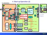
Protection Circuit Block Diagram 1 of 2 (TC-P**S60)
2 Blinks
Shorted (42/50 inch)
Fast 3 Blinks
Shorted (55/60/65 inch)
2 Blinks
Missing
P15V
(
“
42/50)
(
“
55/
60/65)
SN
(
“
42)
Содержание S Series
Страница 4: ...Slide 3 1 Board Layout and connectors Location ...
Страница 10: ...Slide 9 2 Voltage Distribution ...
Страница 16: ...Slide 15 3 Standby Operation ...
Страница 23: ...Slide 22 4 Start up Operation ...
Страница 29: ...Slide 28 5 SOS Detect Circuit Explanation Shutdown ...
Страница 67: ...Slide 66 6 Blinking Code and No power Troubleshooting Flowchart ...
Страница 91: ...Slide 90 Video Lines Troubleshooting ...
Страница 95: ...Slide 94 Test Patterns ...
Страница 96: ...Slide 95 Defective Panel Drive IC ...
Страница 97: ...Slide 96 7 Electric pen and Bluetooth Troubleshooting Flowchart ...
Страница 102: ...Slide 101 8 Wireless LAN adaptor Troubleshooting Flowchart ...
Страница 106: ...Slide 105 9 Data Copy using USB Memory ...
Страница 108: ...Slide 107 ...
Страница 109: ...Slide 108 ...


