


5.1.11. DEFEATING THE AUTO TRACKING
To defeat the Auto Tracking Function, place the instrument in
the STOP mode and place a jumper between TP6003 and
TP6009 on the TV/VCR Main C.B.A. The tracking will be
placed in the neutral position.
5.1.12. HOW TO SET TRACKING TO THE
NEUTRAL POSITION
Ejecting the cassette tape and then reinserting it will reset the
tracking to the Neutral position.
5.1.13. BLACK SCREWS ON THE
CHASSIS
Black Screws are used on the Mechanism Chassis to identify
screws that require adjustment.
5.1.14. HOW TO RESET ALL
COMBINATION VCR MEMORY
FUNCTIONS
To reset (clear) the select language, channel auto set and set
clock functions to their initial power on condition (power on, no
cassette inserted), hold down the PLAY and FF buttons on the
unit together for more than 5 seconds.
Power will shut off.
5.1.15. HOW TO CONFIRM AUTO CLOCK
SET FEATURE
1. Connect an RF cable from the output of one unit to the input
of the test unit.
2. Select corresponding RF channels.
3. Playback a recording of P.B.S. channel including clock set
data and confirm this feature.
5.1.16. VARIABLE VOLTAGE ISOLATION
TRANSFORMER
An Isolation Transformer should always be used during the
servicing of Combination VCR whose chassis is not isolated
from the AC power line. Use a transformer of adequate power
rating as this protects the technician from accidents resulting in
personal injury from electrical shocks. It will also protect
Combination VCR from being damaged by accidental shorting
that may occur during servicing.
Also, when troubleshooting the above type of Power Supply
Circuit, a variable isolation transformer is required in order to
increase the input voltage slowly.
5.1.17. SPECIAL NOTE
All integrated circuits and many other semiconductor devices
are electrostatically sensitive and therefore require the special
handling techniques described under the
"ELECTROSTATICALLY SENSITIVE (ES) DEVICES" section
of this service manual.
5.1.18. REPLACEMENT PROCEDURE FOR
LEADLESS (CHIP) COMPONENTS
The
following
procedures
are
recommended
for
the
replacement of the leadless components used in this unit.
1. Preparation for replacement
a. Soldering Iron
Use a pencil-type soldering iron that uses less than 30
watts.
b. Solder
Eutectic Solder (Tin 63 %, Lead 37 %) is recommended.
c.
Soldering time
Do not apply heat for more than 4 seconds.
d. Preheating
Leadless
capacitor
must
be
preheated
before
installation. -(266 °F ~ 302 °F)
(130 °C ~150 °C) for about two minutes.
Note:
a. Leadless
components
must
not
be
reused
after
removal.
b. Excessive mechanical
stress and
rubbing of the
component electrode must be avoided.
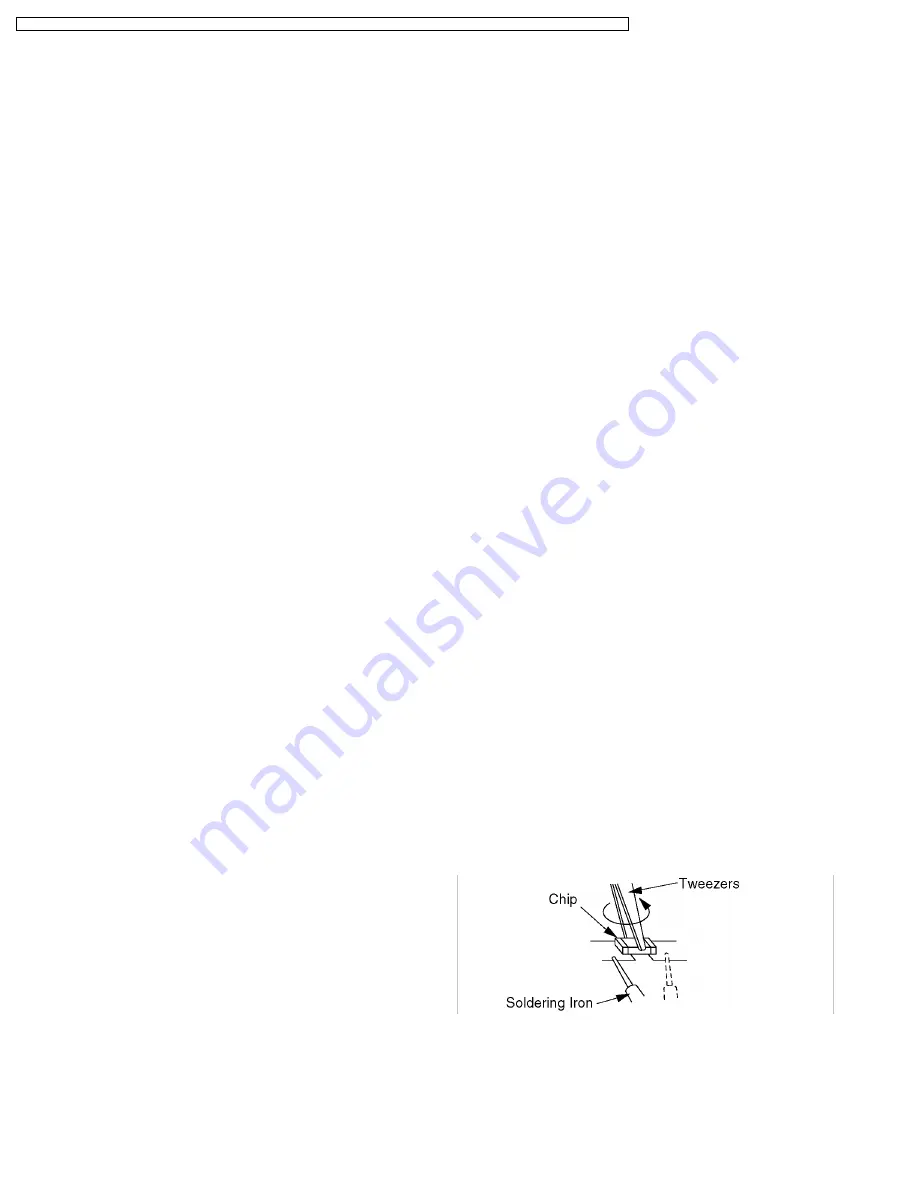
2. Removing the leadless component
Grasp the leadless component body with tweezers and
alternately apply heat to both electrodes. When the solder
on
both
electrodes
is melted, remove
the leadless
component with a twisting motion.
Note:
a. Do not attempt to lift the component off the board until
the component is completely disconnected from the
board by a twisting action.
b. Be careful not to break the copper foil on the printed
circuit board.
Fig. 9-1
3. Installing the leadless component
a. Presolder the contact points on the circuit board.
20
PVQ-1310 / PV-C1320 / PV-C1330W / VV-1300 / VV-1310W / PV-C1340 / PV-C1350W / PV-C2010 / PV-C2020 / PV-C2030W / VV-2000 / PV-C2060
Содержание QUASAR PV-C1320
Страница 59: ...59 PVQ 1310 PV C1320 PV C1330W VV 1300 VV 1310W PV C1340 PV C1350W PV C2010 PV C2020 PV C2030W VV 2000 PV C2060...
Страница 60: ...60 PVQ 1310 PV C1320 PV C1330W VV 1300 VV 1310W PV C1340 PV C1350W PV C2010 PV C2020 PV C2030W VV 2000 PV C2060...
Страница 106: ...106 PVQ 1310 PV C1320 PV C1330W VV 1300 VV 1310W PV C1340 PV C1350W PV C2010 PV C2020 PV C2030W VV 2000 PV C2060...


