


14
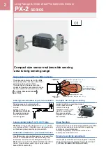
Long Range & Wide Area Photoelectric Sensor
PX-2
SERIES
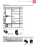
DIMENSIONS (Unit: mm
in
)
The CAD data can be downloaded from our website.
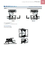
MS-NX5-1
Auxiliary sensor mounting bracket (Accessory for
PX-SB1
)
t 2
t 0.079
9.4
0.370
5.2
0.205
6.4
0.252
25
0.984
12
0.472
22
0.866
ø6.4
ø0.252
hole
40
1.575
5°
5°
4.5
0.177
50
1.969
15
0.591
30
1.181
72
2.835
25
0.984
6
0.236
25
0.984
25
0.984
29
1.142
2-ø4.5
ø0.177
holes
R55.9
R2.201
Assembly dimensions
25
0.984
6.4
0.252
ø6.4
ø0.252
12
0.472
t 2
t 0.079
Beam axis
10°
40
1.575
1
0.039
72
2.835
22
0.866
5.2
0.205
21
0.827
40
1.575
(43)
(1.693)
11
0.433
50.5
1.988
Material: Cold rolled carbon steel (SPCC)
(Uni-chrome plated)
Two M4 (length 25 mm
0.984 in
)
screws with washers and two M4 nuts are attached.
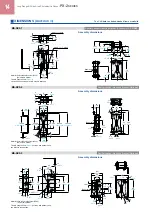
MS-NX5-2
Assembly dimensions
MS-NX5-3
Auxiliary sensor mounting bracket (Optional)
Assembly dimensions
Material: Cold rolled carbon steel (SPCC)
(Uni-chrome plated)
Two M4 (length 25 mm
0.984 in
) screws with washers and
two M4 nuts are attached.
Material: Cold rolled carbon steel (SPCC)
(Uni-chrome plated)
Two M4 (length 25 mm
0.984 in
) screws with washers and
two M4 nuts are attached.
Auxiliary sensor mounting bracket (Optional)
6
0.236
25
0.984
70 ±0.3
2.756 ±0.012
t 2
t 0.079
6
0.236
14
0.551
17
0.669
29
1.142
10
0.394
8
0.315
40
1.575
37
1.457
6
0.236
6.4
0.252
50 ±0.2
1.969 ±0.008
4.5
0.177
5°
5°
15
0.591
25
0.984
12
0.472
30
1.181
36.6
1.441
90 ±0.2
3.543 ±0.008
104 ±0.3
4.094 ±0.012
R28
R1.102
5
0.197
t 2
t 0.079
Beam axis
55.5
2.185
10°
90
3.543
104
4.094
6
0.236
6.4
0.252
14
0.551
25
0.984
11
0.433
40
1.575
t 2
t 0.079
50
1.969
18
0.709
25
0.984
5.5
0.217
6
0.236
2-ø4.5
ø0.177
holes
4.5
0.177
5°
5°
5.5
0.217
25
0.984
45
1.772
30
1.181
50
1.969
64
2.520
22
0.866
12
0.472
9.5
0.374
6.4
0.252
5
0.197
6
0.236
42
1.654
6.4
0.252
6.4
0.252
R55.9 ±0.2
R2.201 ±0.008
t 2
t 0.079
45
1.772
21
0.827
6.4
0.252
6.4
0.252
1
0.039
Beam axis
64
2.520
18
0.709
6
0.236
5
0.197
12
0.472
(43)
(1.693)
22
0.866
10.5
0.413
42
1.654
40
1.575
10°