background image

E

NGLISH

-13

Preparation

12-E

NGLISH

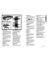
#

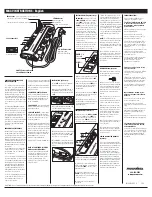
Remote control signal receptor

(page 20)

$

Security lock

This can be used to connect a
commercially-available theft-
prevention cable (manufactured
by Kensington). This security lock
is compatible with the Microsaver
Security System from
Kensington. Contact details for
this company are given below.
Kensington Technology Group
ACCO Brands Inc.
2855 Campus Drive
San Mateo, CA 94403 USA
Tel (650)572-2700
Fax (650)572-9675
http://www.kensington.com/
http://www.gravis.com/

NOTE:

B

Information given above may be
changed in future.

%

Lamp unit holder

(page 49)

&

Carrying handle

'

Air outlet port

Do not cover this port.
When you change the direction of

the air flow out of the outlet port,
make sure that the MAIN
POWER is “OFF” and the
projector is cooled down.

WARNING

Do not bring your hands or other
objects close to the air outlet
port.

B

Heated air comes out of the air
outlet port. Do not bring your
hands or face, or objects which
cannot withstand heat close to
this port, otherwise burns or
damage could result.

NOTE:

B

During projection of an image, the
cooling fan will operate, emitting
a small noise as it operates.
Turning the lamp on or off will
cause this noise to increase a
little.

B

By using the OPTION2 menu to
set “LAMP POWER” to “LOW”,
the operating sound of the fan
can be reduced. (Refer to page
41.)

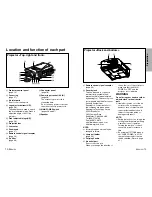
Projector <Back and bottom>

Location and function of each part

#

Projector control panel

(page 14)

$

Focus ring

(page 27)

%

Air inlet ports

Do not cover these ports.

&

Leg adjuster buttons(L/R)

(page 26)
These buttons are used to unlock
the front adjustable legs. Press to
adjust the angle of tilt of the
projector.

'

Front adjustable legs(L/R)

(page 26)

(

Projection lens

)

Lens cover

*

Zoom knob

(page 27)

+

Remote control signal receptor

(page 20)

,

Air filter

(page 48)

-

Connector panel 

(page 16)

.

Power input socket (AC IN)

(page 26)
The accessory power cord is
connected here.
Do not use any power cord other
than the accessory power cord.

/

MAIN POWER switch

(pages 26 and 27)

0

Speaker

Projector <Top, right and front>

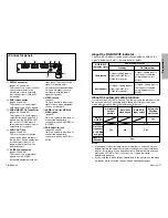
#

$

'
(
)

&

'

+

*

,

%

%

/

0

.

&

-

'

#

$

%

&

Содержание PT-L520E

Страница 1: ...LISH R Before operating this product please read the instructions carefully and save this manual for future use LCD Projector Operating Instructions Model No PT L720E PT L520E R TQBJ 0105 3 Commercial Use ...

Страница 2: ... symbol or coloured GREEN or GREEN AND YELLOW The wire which is coloured BLUE must be connected to the terminal in the plug which is marked with the letter N or coloured BLACK The wire which is coloured BROWN must be connected to the terminal in the plug which is marked with the letter L or coloured RED How to replace the fuse Open the fuse compartment with a screwdriver and replace the fuse ASA 1...

Страница 3: ...e Pull the power cord out from the wall outlet and wipe it with a dry cloth BIf not using the projector for an extended period of time pull the power cord plug out from the wall outlet 4 ENGLISH Contents Preparation IMPORTANT SAFETY NOTICE 2 Precautions with regard to safety 5 Accessories 9 Precautions on handling 10 Location and function of each part 12 About the RGB INPUT indicator 17 About the ...

Страница 4: ...sult Do not do anything that might damage the power cord or the power cord plug BDo not damage the power cord make any modifications to it place it near any hot objects bend it excessively twist it pull it place heavy objects on top of it or wrap it into a bundle BIf the power cord is used while damaged electric shocks short circuits or fire may result BAsk an Authorised Service Centre to carry ou...

Страница 5: ...ice Centre to clean inside the projector at least once a year BIf dust is left to build up inside the projector without being cleaned out it can result in fire or problems with operation BIt is a good idea to clean the inside of the projector before the season for humid weather arrives Ask your nearest Authorised Service Centre to clean the projector when required Please discuss with the Authorise...

Страница 6: ...the following at all times when setting up the projector Avoid setting up in places which are subject to vibration or shocks If the projector is set up in locations with strong vibration such as near a motor or if it is installed inside a vehicle or on board a ship the projector may be subjected to vibration or shocks which can damage the internal parts and cause malfunctions or accidents Accordin...

Страница 7: ...Do not bring your hands or face or objects which cannot withstand heat close to this port otherwise burns or damage could result NOTE BDuring projection of an image the cooling fan will operate emitting a small noise as it operates Turning the lamp on or off will cause this noise to increase a little BBy using the OPTION2 menu to set LAMP POWER to LOW the operating sound of the fan can be reduced ...

Страница 8: ...e 19 ENTER button page 30 This button is used to accept and to activate items selected in the on screen menus When in computer operating mode this button on the remote control unit operates differently page 19 Laser emitter page 18 Infrared emitter page 20 0Click button page 19 This button can be used when the operating mode select switch is moved to the left Computer 1PAGE button page 19 This but...

Страница 9: ... one system is provided so connect the appropriate connector when using RGB1 or RGB2 About the RGB INPUT indicator The RGB INPUT indicator can be used to check whether an RGB YPBPR signal is being input Refer to the table below for details RGB INPUT indicator status Power supply status On projecting Standby A signal is being input to either the RGB1 IN or RGB2 IN connector A signal is being input ...

Страница 10: ...pecified herein may result in hazardous radiation exposure BThis remote control unit cannot be repaired To operate a personal computer with the remote control move the operating mode Computer Projector select switch to the left Computer Operation BFGIHbuttons While gently pressing the button with your thumb move your thumb up down and to the left and right to move the mouse cursor in the same dire...

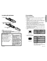
Страница 11: ...f the remote control signal receptors on the front or rear of the projector the operating range is within approximately 7 m 23 from the surfaces of the receptors Furthermore the remote control unit can be operated from an angle of 30 to the left or right and 15 above or below the receptors Open the cover AAA batteries two Insert the batteries so that the polarities are correct and then close the c...

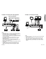
Страница 12: ... one audio system circuit is available for the AUDIO IN L R jacks for S VIDEO VIDEO signals so if you wish to change the audio input source you will need to remove and insert the appropriate plugs BOnly one audio system circuit is available for the RGB AUDIO IN jacks so if you wish to change the audio input source you will need to remove and insert the appropriate plugs BIf an audio system is conn...

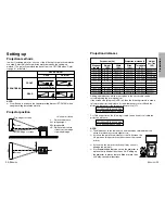
Страница 13: ...ctor position DESK CEILING DESK CEILING H1 L L SH SW 9 6 3 8 L Projection distance SH Image height SW Image width H1 Distance from centre of lens to bottom edge of projected image Top edge of screen Screen Bottom edge of screen Screen Projection distances Screen size 4 3 Diagonal length Height SH Width SW Projection distance L Height position H1 Wide LW Telephoto LT Units mm inch Setting up dimens...

Страница 14: ...ting Be careful not to switch off the MAIN POWER switch of the projector unplug the power cord from the electrical outlet or turn off in line switches such as tabletop power switches Press the MAIN POWER switch to the O side to turn off the power NOTE BAfter the power is turned off the lamp unit will take some time to cool down If you turn the power back on again before the lamp unit has cooled do...

Страница 15: ...ge 37 When an RGB YPBPR signal is being input On screen menus Menu screens The various settings and adjustments for this projector can be carried out by selecting the operations from on screen menus The general arrangement of these menus is shown below MAIN MENU OPTION2 menu page 40 LANGUAGE menu page 42 SHUTTER function page 42 NOTE BKeystone distortion of the on screen display will not be correc...

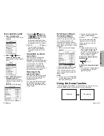
Страница 16: ...enu MENU KEYSTONE PICTURE POSITION INDEX WINDOW SHUTTER AUDIO LANGUAGE OPTION1 OPTION2 SELECT ENTER MENU KEYSTONE PICTURE POSITION INDEX WINDOW SHUTTER AUDIO LANGUAGE OPTION1 OPTION2 SELECT ENTER PICTURE PICTURE MODE STANDARD COLOR TEMP STANDARD COLOR 32 TINT 32 BRIGHT 32 CONTRAST 32 SHARPNESS 2 NR 1 TV SYSTEM AUTO1 STANDARD SELECT ADJ ESC Press the F F or G G buttons to select an item and then pr...

Страница 17: ...distortion Picture condition Operation Press the H H button Press the I I button Press the MENU button to return to the previous screen NOTE BIf you press the AUTO SETUP button after correcting the keystone distortion manually the automatic keystone correction function will operate and the corrected picture will return to its previous incorrect condition To prevent this from happening you can set ...

Страница 18: ...ANDARD HIGH LOW PICTURE MODE STANDARD DYNAMIC NATURAL PICTURE PICTURE MODE STANDARD COLOR TEMP STANDARD BRIGHT 32 CONTRAST 32 SHARPNESS 0 W BAL R 32 W BAL G 32 W BAL B 32 SIGNAL MODE SVGA STANDARD SELECT ADJ ESC PICTURE PICTURE MODE STANDARD COLOR TEMP STANDARD COLOR 32 TINT 32 BRIGHT 32 CONTRAST 32 SHARPNESS 2 NR 1 TV SYSTEM AUTO1 STILL MODE OFF STANDARD SELECT ADJ ESC When an RGB signal is being...

Страница 19: ...Adjusting the position POSITION H POSITION 64 V POSITION 32 DOT CLOCK 32 CLOCK PHASE 16 ASPECT 4 3 RESIZING ON STANDARD SELECT ENTER ESC POSITION H POSITION 32 V POSITION 16 ASPECT 4 3 RESIZING ON STANDARD SELECT ENTER ESC When the input signal is RGB first press the AUTO SETUP button to initiate automatic positioning If the optimum setting is not obtained when AUTO SETUP is carried out adjust by ...

Страница 20: ...distortion may occur around the edges of the picture so that part of the picture is no longer visible Such programmes should be viewed in 4 3 mode to give proper consideration to the aims and intentions of the original programme s creator S1 video signals BS1 video signals are a type of video signal with an aspect ratio of 16 9 which include a detector signal This detector signal is output by some...

Страница 21: ...POWER HIGH LAMP RUNTIME 10H FUNC 1 INDEX CONTROL KEY ON SELECT ADJ ESC Advanced Operation SXGA MODE This setting is only for an SXGA signal SXGA Select this item normally SXGA When the projected image is contracted vertically select this item BACK COLOR This sets the colour which is projected onto the screen when no signal is being input to the projector FRONT REAR This setting should be changed i...

Страница 22: ...ng picture on the screen CONTROL KEY ON OFF Press the FUNC1 button You can also select INDEX WINDOW from the MAIN MENU screen and then press the ENTER button NOTE BThe aspect ratio of the screen changes and the image is vertically elongated in comparison to a normal image Still picture Moving picture Use the F and G buttons to select a screen size When the screen size is changed the picture s aspe...

Страница 23: ...al computer Pin No Communications settings Signal name Contents 1 5 6 9 NC TXD Transmitted data RXD Received data NC GND DSR CTS Connected internally RTS NC D SUB 9 pin connector seen from outside Signal level RS 232C Asynchronous Sync method Baud rate Parity 9600 bps None Character length 8 bits Stop bit 1 bit X parameter None S parameter None STX Command Parameter ETX Control commands The comman...

Страница 24: ...ocedure on page 27 and then clean the air filter refer to page 48 Possible cause Remedy The surrounding temperature or the temperature inside the projector has become dangerously high causing the lamp unit to be automatically shut off Flashing red Lamp unit off TEMP indicator Remedy Problem Indicator display Flashing red It is nearly time to replace the lamp unit Illuminated red An abnormality has...

Страница 25: ...when 2000 hours of use have been reached NOTE BThe usage hours explained above are for use when the HIGH setting has been selected for LAMP POWER in the OPTION2 menu If the LOW setting is selected the brightness of the lamp will be less and life of the lamp can be extended BWhile 2000 hours is the intended replacement interval it is not a period of time covered by warranty Cleaning and replacing t...

Страница 26: ... screen and then use the F and G buttons to select LAMP RUNTIME Press and hold the ENTER button for approximately 3 seconds The LAMP RUNTIME will change to TIME RESET POWER OFF NOTE BIf the MENU button is pressed the lamp time resetting screen will be cancelled Turn off the power This will reset the cumulative usage time for the lamp unit to zero Refer to page 27 for details on how to turn off the...

Страница 27: ...ojector may not be adjusted correctly BThe audio signal source may not be connected properly BThe volume adjustment may be at the lowest possible setting Refer to pages 15 and 28 BA cable may be connected to the AUDIO OUT jack Problem Possible cause BThe batteries may be weak BThe batteries may not be inserted correctly Refer to page 20 BThe remote control signal receptor on the projector may be o...

Страница 28: ...ange Approx 7 m 23 when operated directly in front of signal receptor Weight 108 g 3 8 ozs including batteries Dimensions Width 33 mm 1 9 32 Length 168 mm 6 19 32 Height 40 mm 1 9 16 Options Ceiling bracket ET PK730 Wireless mouse receiver ET RMRC1 Wide conversion lens ET LEC701 Specifications Power supply 100 V 240 V 50 Hz 60 Hz Power consumption 300 W During standby when fan is stopped Approx 1 ...

Страница 29: ... 35 000 66 667 30 240 A A OK OK RGB 640 x 480 37 861 72 809 31 500 A A OK OK RGB 640 x 480 37 500 75 000 31 500 A A OK OK RGB 640 x 480 43 269 85 008 36 000 A A OK OK RGB 800 x 600 35 156 56 250 36 000 A AA OK RGB 800 x 600 37 879 60 317 40 000 A AA OK RGB 800 x 600 48 077 72 188 50 000 A AA OK RGB 800 x 600 46 875 75 000 49 500 A AA OK RGB 800 x 600 53 674 85 061 56 250 A AA OK RGB 832 x 624 49 7...

Страница 30: ...marks of International Business Machines Corporation BMacintosh is a registered trademark of Apple Computer Inc BS VGA is a registered trademark of the Video Electronics Standards Association BWindows is a registered trademark of Microsoft Corporation All other trademarks are the property of the various trademark owners ...

Отзывы: