- 19 -
Service Manual
Pincushion Adjustment (D05)
Procedure:
1.
Cover Red and Blue Lenses.
2.
Apply a crosshatch pattern.
3.
Set DAC D0F from 0 to 1 (disabling digital
convergence).
4.
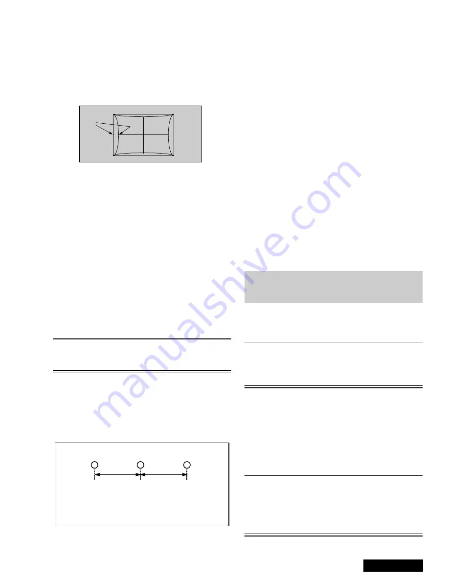
Adjust DAC D05 (Pincushion) by pressing CH up-
down and confirm that size is 30±5mm at “A” (See
Figure 33)
Figure 33. Pincushion Adjustment
5.
If Trapezoid adjustment is required after this
adjustment, perform trapezoid adjustment.
6.
Enable digital convergence by changing DAC D0F
from 1 to 0 and remove caps from lenses.
Centering Magnets Adjustment
Procedures:
1.
Apply a monoscope pattern.
2.
Cover the red and blue lens so only the green lens
is projecting the monoscope pattern.
3.
Set DAC D0F from 0 to 1 (disabling digital
convergence).
4.
Loosen the deflection coil screw on the green CRT.
5.
Adjust green deflection coil until the horizontal
center line is in line with the grid and is leveled.
6.
Adjust centering magnets until the green pattern is
equal on left and right. Adjust also for horizontal
and vertical tilt.
Note: Push deflection coil to top of CRT neck,
then tighten deflection screw after adjusting
each CRT centering and Tilt.
7.
Transfer lens cover from red to green and project
red only. Adjust deflection coil until the horizontal
center line matches the pattern of the grid and is
leveled.
8.
Adjust red centering magnets until the monoscope
pattern center is at the appropriate distance as
indicated on Figure 34.
Figure 34. Centering Magnets Adjustment.
9.
Transfer lens cover from blue to red, so that blue is
projected.
10. Adjust blue deflection coil until the horizontal
center line matches the pattern of the grid and is
leveled.
11. Adjust blue centering magnets until the monoscope
pattern center is at the appropriate distance as
indicated on Figure 34.
12. Enable digital convergence by changing DAC D0F
from 1 to 0.
13. Following the adjustment, make sure that all
deflection coils are pushed completely toward the
CRT cones and that all screws are tightened.
Horizontal Size Adjustment (D03)
This is the manual adjustment of horizontal size that is
included in the automatic convergence adjustment.
1.
Apply a monoscope pattern.
2.
Set DAC D0F from 0 to 1 (disabling digital
convergence).
3.
Cover both red and blue lens.
4.
In service mode, adjust H-Size DAC (D03) until the
picture horizontal size is 5.0
±
0.2 lines at left side
of screen.
5.
Enable digital convergence by changing DAC D0F
from 1 to 0.
6.
Remove lens covers.
Convergence Adjustment
Turn PTV on and allow it to warm up for 30
minutes prior to making adjustments
(WHITE PATTERN).
Note: This PTV uses the scheme described
below to correct for misconvergence of the
three CRT projection tubes. There are
various modes to this operation.
Preparation:
Place the Convergence Alignment Template (see
“Convergence Alignment Template” on page 24) over
the PTV screen. Align the center lines of the template
with the mechanical center markers on the PTV screen
frame. If the template is not available, create one using
the dimensions provided in “Convergence Alignment
Template” on page 24.
Remote control must be used during the procedure.
Note: Apply the Convergence Alignment Template to
the PTV screen frame to converge the Green
Raster only. Remove the Convergence
Alignment Template following this alignment.
The red and blue rasters can then be aligned
to the green raster.
“A”
R
G
d
d
PT-51” 28 mm
PT-61” 17 mm
d measured in mm
B
Note: It is strongly recommended to first read and
understand the following section prior to
make any adjustment.
Содержание PT-51G36CE
Страница 17: ... 50 PT 51G36E EC A Board Schematic Left Portion ...
Страница 19: ... 52 PT 51G36E EC P Board Schematic Left Portion ...
Страница 21: ... 54 PT 51G36E EC X Board Schematic Left Portion ...


