107
AHU Kit – Installation Instructions –
11/2021
Control
7
6.
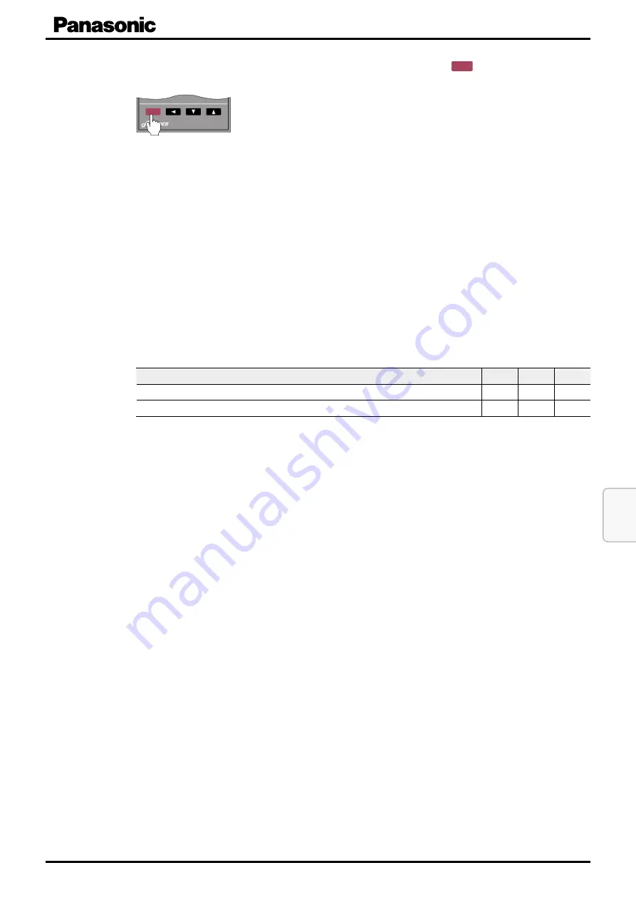
Confirm the complete parametrization by pressing and holding the
SSEETT
button for
approximatedly 3 seconds.
TR-16e
SSEETT
1 x for 3 sec.
9
Parametrization is now complete. The PV and SV displays have returned to showing the current
temperature and the set temperature values respectively.
7.2.3 Initial Settings
Depending on how the thermostat is used in each individual application, its settings must be adjust-
ed for the relevant case.
Case 1: Controlling the room supply air temperature
To set the thermostat for controlling the room supply air temperature, perform the following steps:
1.
Open the AHU Kit enclosure (see →
4.1.1 Installation of AHU Kit – MAH2/PAH2 – step 3,
2. On the thermostat, switch to PID mode by entering the “Parameter” menu and set parameters
P, I and D to the values given below (see →
7.2.2 Thermostat – Operation – Changing values in
).
AHU situation
P
I
D
(a) Capacity
high
and
air
volume
flow
low
7
120
3
(b) Capacity
low
and
air
volume
flow
high
3
180
10
These PID settings are intended to respond to AHU situations, where either the required
capacity is rather high (close to the upper limit of the nominal AHU kit capacity) while at the
same time the air volume flow is rather low (a), or vice versa (b).
If the initial PID setting results in an unstable temperature during operation, these values may
be adjusted manually at a later stage.
3. On the thermostat, switch to cooling or heating mode, depending on the AHU requirements
(for AHU Kit models equipped with thermostat TR-16, see →
7.2.2 Thermostat – Operation –
Switching from “heating mode” to “cooling mode”, p. 105
; for models with TR-16e, this
procedure is not required).
4. On the thermostat, change the set temperature value (T
set
) as required
(see →
7.2.2 Thermostat – Operation – Changing the set temperature value, p. 102
In this case, the set temperature value represents the desired room supply air temperature.
5. On the AHU kit’s terminal connector of section F, remove the jumper (JP1) between terminals
“M2-5” and “M2-6 (FREE)”, in order to activate the 0-10 V control mode for the thermostat.
6.
Close the AHU Kit enclosure again (see →
Содержание PAW-280PAH3M-1
Страница 2: ...Notes ...
Страница 113: ...Notes ...


