background image

No. 
DS-PAN1311/21USB 

REV. 

1.1 

PAGE 


3  of  11 


Quick Start Guide


Evaluation Board (EVB) PAN1311/21 USB


DATE 


15.09.2011 


PANASONIC ELECTRONIC DEVICES EUROPE 

GmbH 


DESIGNED 

Erstellt 

IW 


2. INTRODUCTION 

This  document  should  provide  the  minimum  knowledge  needed  to  establish  a  simple 
connection  between  two  PAN1321ETU  USB  Evaluation  Boards  (EVB)  using  Infineon 

eBMU_SPP_Toolbox 

software.  For  this  limited  information  is  granted.  To  learn  about  all 

aspects of the software please refer to the related documents listed below. 


2.1 RELATED DOCUMENTS 

For  further  information  on  Infineon 

eBMU_SPP_Toolbox 

software  and  it’s  implemented  AT 

command set please refer to: 


PAN13x1_ReleaseNote_SPP_AT_SW08_V1.8_RN_Rev1.0_DRAFT 


PAN13x1_ReleaseNote_SPP_AT_SW21_V2.1_RN_Rev1.0_DRAFT -iPhone version 


PAN13x1_SPP_AT_UserManual_SoftwareDescription_Rev5.0 DRAFT 


PAN1321_AN_DesignGuide_Rev2 1 


User's_Manual_PAN1311_V20.xx_Rev1.1 


User's_Manual_PAN1321_V20.xx_Rev3.1 


4. FUNCTIONAL OVERVIEW 

 
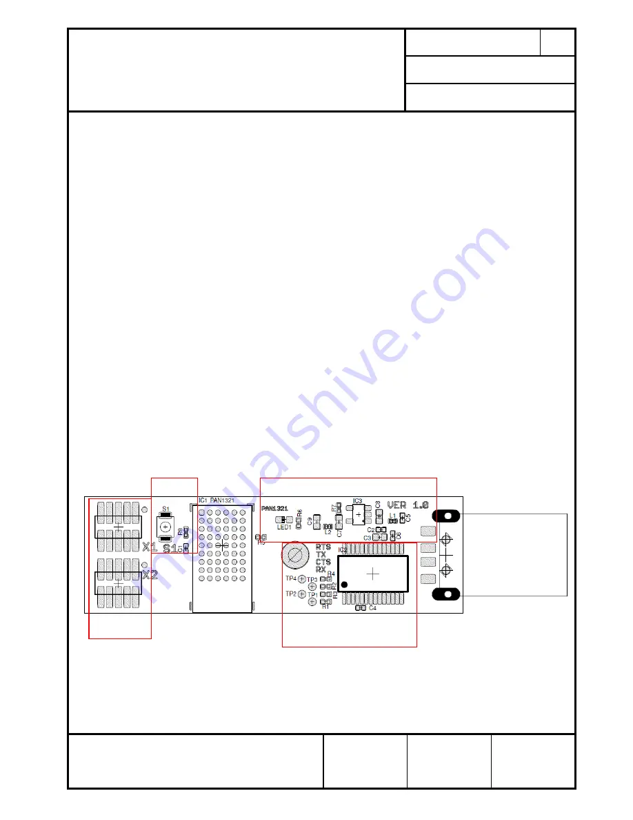
The figure below shows an overview of the Evaluation Board. If there is the need to connect 
your µController to the EVB please de-solder R1, R2, R3, R4. 


For more details please refer also to the schematic in chapter Schematic.  


Figure 2 : Evaluation Board Overview 


Hardware 

Reset 

UART to USB 

Converter Section 

For interfaces 

description refer to 

schematic 

Power Supply 

section 

Содержание PAN1311/21 USB

Страница 1: ...1 21USB REV 1 1 PAGE 1 of 11 Quick Start Guide Evaluation Board EVB PAN1311 21 USB DATE 15 09 2011 PANASONIC ELECTRONIC DEVICES EUROPE GmbH DESIGNED Erstellt IW Quick Start Guide Evaluation Board EVB PAN1311 21 USB ...

Страница 2: ...rstellt IW 1 CONTENT 1 Content 2 2 Introduction 3 2 1 Related documents 3 4 Functional overview 3 5 Connection setup 4 5 1 Software start and navigation 4 5 2 Port configuration 5 5 3 Firmware handling 6 5 4 Command tab navigation 7 5 5 Creating a connection 8 6 Schematic 9 7 Document Information 10 8 General Information 11 8 1 Waiver 11 9 Life Support Policy 11 ...

Страница 3: ...fineon eBMU_SPP_Toolbox software and it s implemented AT command set please refer to PAN13x1_ReleaseNote_SPP_AT_SW08_V1 8_RN_Rev1 0_DRAFT PAN13x1_ReleaseNote_SPP_AT_SW21_V2 1_RN_Rev1 0_DRAFT iPhone version PAN13x1_SPP_AT_UserManual_SoftwareDescription_Rev5 0 DRAFT PAN1321_AN_DesignGuide_Rev2 1 User s_Manual_PAN1311_V20 xx_Rev1 1 User s_Manual_PAN1321_V20 xx_Rev3 1 4 FUNCTIONAL OVERVIEW The figure ...

Страница 4: ... DESIGNED Erstellt IW 5 CONNECTION SETUP This chapter describes how to use the eBMU_SPP_Toolbox software in order to send simple data packages from one EVB to the other 5 1 SOFTWARE START AND NAVIGATION Browse to the folder where the eBMU_SPP_Toolbox exe file is located and start it The user interface figure 2 is shown Figure 4 Toolbox start up screen ...

Страница 5: ...he installation folder On the settings tab the communication via COM port is handled It is possible to set a number of default parameters for both EVBs and to save load all the changes made to this page saving the settings will also make the program remember the selected port numbers Please select the right port numbers for both EVBs found at Windows OS control panel system hardware device manager...

Страница 6: ... g 0003199E8B73 and oscillator trim value Make sure that the Production mode is enabled before any of these buttons on this tab are used To do this mark On and confirm with a click on Production mode The text field should inform you about of success of this procedure Be advised to do a hardware reset push button on EVB after all changes were made Please note The BD_Address and OSC_Trim value have ...

Страница 7: ...coding identifying commands by their intended usage Yellow Settings and informational commands Pink Security related commands Green Connection related Red Disconnection commands Blue Data transfer Light blue Accept connection White Sniff during connection Figure 7 Command tab and used commands For simple data transfer find the needed commands marked in figure 5 The Custom Command button can be use...

Страница 8: ...e option 1 EVB A will auto accept connection requests from now on Device A is now ready for connection 4 Get the address of EVB A with the help of Read BD Address In the text field you will find the desired information e g RRBDRES 0003199E8B73 With this Device A can be addressed when 5 issuing Connection Request from Device B Type or copy the BD address of Device A into the BD Address 0x text fiel...

Страница 9: ...No DS PAN1311 21USB REV 1 1 PAGE 9 of 11 Quick Start Guide Evaluation Board EVB PAN1311 21 USB DATE 15 09 2011 PANASONIC ELECTRONIC DEVICES EUROPE GmbH DESIGNED Erstellt IW 6 SCHEMATIC ...

Страница 10: ...SB DATE 15 09 2011 PANASONIC ELECTRONIC DEVICES EUROPE GmbH DESIGNED Erstellt IW 7 DOCUMENT INFORMATION Revision Version Date Datum Modification Remarks Änderungen Bemerkungen 1 0 18 04 2011 Initial version 1 1 15 09 2011 Updated documentation information in chapter 2 1 Table 3 Document version ...

Страница 11: ...Panasonic rejects any liability or product warranty for Engineering Samples In particular Panasonic waives liability for damages caused by the use of the Engineering Sample other than for Evaluation Purposes particularly the installation or integration in an other product to be sold by Customer deviation or lapse in function of Engineering Sample improper use of Engineering Samples Panasonic waive...

Отзывы: