


Содержание Palmcorder VDR-D100
Страница 1: ...DVD DVC Camera Seminar VDR D100 200 300 and PV GS29 39 Panasonic...
Страница 3: ...DVD Camera Comparison...
Страница 4: ...Recording Playback Media DVD Camera...
Страница 5: ...Discs that can not be used in this unit...
Страница 6: ...Camera Structure VDR D100 200...
Страница 7: ...Camera Structure VDR D300...
Страница 8: ...Camera Structure VDR D300...
Страница 10: ...Also used for VDR D100 200 Also used for VDR D100 200 Also used for VDR D100 200 Extension Cables for VDR D300...
Страница 11: ...Light box Charts etc for all DVD Cameras Adjustment procedure for the DVD and the DVC Cameras is the same...
Страница 12: ...Adjustment Necessary After Board Replacement...
Страница 24: ...Service Position VDR D100 200...
Страница 28: ...Update Procedure for ARM FW...
Страница 35: ...Update Procedure for DVD Drive F W PC with WindowsXP No Disc inserted in Camera Connect to DC Cord AC Adaptor...
Страница 37: ...Update Procedure for DVD Drive F W 5 Click DWL2WIN double click 6 Click DownLoad icon 5 6...
Страница 39: ...Service Mode Version Check Make sure that the USB Cable is disconnected...
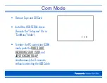
Страница 42: ...Troubleshooting...
Страница 43: ...VDR D100 105 200 IC Connectors Location Foil Side...
Страница 44: ...VDR D100 105 200 IC Connectors Location Component Side...
Страница 45: ...VDR D300 IC Connectors Location...
Страница 46: ...VDR D300 IC Connectors Location...
Страница 47: ...VDR D300 IC Connectors Location...
Страница 48: ...VDR D300 IC Connectors Location...
Страница 49: ...System Control VDR D100 105 200...
Страница 50: ...Standby Circuit VDR D100 105 200 14 2 8V...
Страница 51: ...Power Supply Components Location...
Страница 52: ...Power ON VDR D100 105 200...
Страница 53: ...Power ON VDR D100 105 200...
Страница 54: ...Overall Diagram VDR D300...
Страница 55: ...Camera Video 1 VDR D300...
Страница 56: ...Video Signal Process VDR D300...
Страница 57: ...Digital Signal Process VDR D300...
Страница 58: ...Audio Video Processor VDR D300...
Страница 59: ...DVC Camera DVC Camera...
Страница 62: ...Service Menu Only perform items 3 in the Service Menu...
Страница 64: ...Service Menu...
Страница 65: ...Service Fixture and Tools...
Страница 66: ...Disassembly Flowchart...
Страница 67: ...Disassembly Flowchart...
Страница 68: ...Bottom Case Unit Removal Ref 7 Remove Screws 3 433 3 537 2 519...
Страница 69: ...Top Unit Removal Ref 50 Remove Screws 3 433 1 519 Pull the Top Unit toward the front...
Страница 71: ...Right Side Assembly Removal...
Страница 73: ...Removal of Front Case Unit 1 Remove the 3 Screws 2 433 1 519 2 Disconnect the Front F P C from Connector FP6...
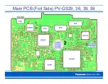
Страница 77: ...Main PCB Foil Side PV GS29 36 39 59...
Страница 78: ...Overall Block Diagram PV GS29 36 39 59...
Страница 79: ...Overall Block Diagram PV GS29 36 39 59...
Страница 80: ...Overall Block Diagram PV GS29 36 39 59...
Страница 82: ...STB Block PV GS29 36 39 59...
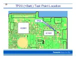
Страница 83: ...TP20 Batt Test Point Location...
Страница 84: ...Power On Block PV GS29 36 39 59...
Страница 85: ...TP15 Power On L Test Point Location...
Страница 86: ...Video Signal Process PV GS29 36 39 59...
Страница 87: ...Video Signal Output Test Point Location MAIN PCB Foil Side...
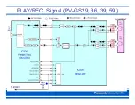
Страница 88: ...PLAY REC Signal PV GS29 36 39 59...
Страница 89: ...PLAY Signal TP PV GS29 36 39 59 MAIN PCB Foil Side...
Страница 90: ...The End...