


PC-EVR Adjustment Program Set-up
1.
Turn on the PC and install the PC-
EVR Adjustment Program into the
PC.
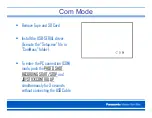
2. Execute the "kdv2006.exe" file by
double clicking to start up the PC-
EVR Adjustment Program. The main
menu will be displayed.
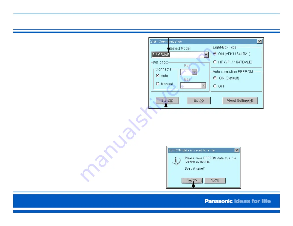
3. Select the model.
4. Turn on the camcorder and set to
PC connection (COM) mode. Then
click "Start"
5. When the communication is complete, the
dialog will appear.
Click "Yes," and "Save" to save the EEPROM
data.
Содержание Palmcorder VDR-D100
Страница 1: ...DVD DVC Camera Seminar VDR D100 200 300 and PV GS29 39 Panasonic...
Страница 3: ...DVD Camera Comparison...
Страница 4: ...Recording Playback Media DVD Camera...
Страница 5: ...Discs that can not be used in this unit...
Страница 6: ...Camera Structure VDR D100 200...
Страница 7: ...Camera Structure VDR D300...
Страница 8: ...Camera Structure VDR D300...
Страница 10: ...Also used for VDR D100 200 Also used for VDR D100 200 Also used for VDR D100 200 Extension Cables for VDR D300...
Страница 11: ...Light box Charts etc for all DVD Cameras Adjustment procedure for the DVD and the DVC Cameras is the same...
Страница 12: ...Adjustment Necessary After Board Replacement...
Страница 24: ...Service Position VDR D100 200...
Страница 28: ...Update Procedure for ARM FW...
Страница 35: ...Update Procedure for DVD Drive F W PC with WindowsXP No Disc inserted in Camera Connect to DC Cord AC Adaptor...
Страница 37: ...Update Procedure for DVD Drive F W 5 Click DWL2WIN double click 6 Click DownLoad icon 5 6...
Страница 39: ...Service Mode Version Check Make sure that the USB Cable is disconnected...
Страница 42: ...Troubleshooting...
Страница 43: ...VDR D100 105 200 IC Connectors Location Foil Side...
Страница 44: ...VDR D100 105 200 IC Connectors Location Component Side...
Страница 45: ...VDR D300 IC Connectors Location...
Страница 46: ...VDR D300 IC Connectors Location...
Страница 47: ...VDR D300 IC Connectors Location...
Страница 48: ...VDR D300 IC Connectors Location...
Страница 49: ...System Control VDR D100 105 200...
Страница 50: ...Standby Circuit VDR D100 105 200 14 2 8V...
Страница 51: ...Power Supply Components Location...
Страница 52: ...Power ON VDR D100 105 200...
Страница 53: ...Power ON VDR D100 105 200...
Страница 54: ...Overall Diagram VDR D300...
Страница 55: ...Camera Video 1 VDR D300...
Страница 56: ...Video Signal Process VDR D300...
Страница 57: ...Digital Signal Process VDR D300...
Страница 58: ...Audio Video Processor VDR D300...
Страница 59: ...DVC Camera DVC Camera...
Страница 62: ...Service Menu Only perform items 3 in the Service Menu...
Страница 64: ...Service Menu...
Страница 65: ...Service Fixture and Tools...
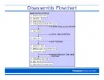
Страница 66: ...Disassembly Flowchart...
Страница 67: ...Disassembly Flowchart...
Страница 68: ...Bottom Case Unit Removal Ref 7 Remove Screws 3 433 3 537 2 519...
Страница 69: ...Top Unit Removal Ref 50 Remove Screws 3 433 1 519 Pull the Top Unit toward the front...
Страница 71: ...Right Side Assembly Removal...
Страница 73: ...Removal of Front Case Unit 1 Remove the 3 Screws 2 433 1 519 2 Disconnect the Front F P C from Connector FP6...
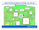
Страница 77: ...Main PCB Foil Side PV GS29 36 39 59...
Страница 78: ...Overall Block Diagram PV GS29 36 39 59...
Страница 79: ...Overall Block Diagram PV GS29 36 39 59...
Страница 80: ...Overall Block Diagram PV GS29 36 39 59...
Страница 82: ...STB Block PV GS29 36 39 59...
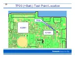
Страница 83: ...TP20 Batt Test Point Location...
Страница 84: ...Power On Block PV GS29 36 39 59...
Страница 85: ...TP15 Power On L Test Point Location...
Страница 86: ...Video Signal Process PV GS29 36 39 59...
Страница 87: ...Video Signal Output Test Point Location MAIN PCB Foil Side...
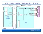
Страница 88: ...PLAY REC Signal PV GS29 36 39 59...
Страница 89: ...PLAY Signal TP PV GS29 36 39 59 MAIN PCB Foil Side...
Страница 90: ...The End...


