background image

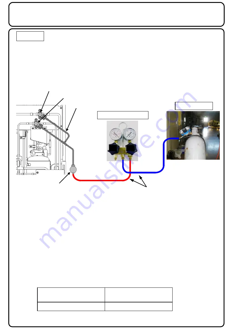
Airtight Test Procedure 

(Execute this test after competing piping work and airtight test but before starting 
heat insulation work) 


1. Piping connection 

     1) Connect the joint valve of the service piping (SPK-TU125) and the manifold gauge set 

exclusively for CO

2

 refrigerant by using a CO

2

 charge hose or 1/4" pipe. 

     2) Connect a nitrogen cylinder and the manifold gauge set by using a CO

 charge hose or  


1/4" pipe. 


2. Airtight test 

     1) Set the evacuation mode in accordance with " Evacuation Mode". 

     2) When carrying out an airtight test of interconnecting piping and load-side equipment  
         (such as showcase and unit cooler), set up the service valves with the front seat. 

         After replacing components of the refrigeration unit and when performing an airtight test of 

the refrigeration unit, use the Mid-position. (The access ports are open.) 


However, at this time, avoid applying the high-pressure side airtight test pressure to 

the low-pressure side. 


Note: 

Airtight test of the refrigeration unit was completed at the time of factory  

shipment. Pressure testing should only be carried out by personal / companies 
who have necessary certification. Consider carefully local regulations and 
EN378. 


Design pressure in Factory 


Caution 

Make sure to close the vacuum valve of CO

2

 manifold gauge set. 

Consider special local regulations and consider Installation of all 
equipment have to be in accordance to pressure directive 2014/68/EU 
and European norm EN378. 

Service piping 

Joint valve 

Nitrogen cylinder 

Charging 

valve 

CO

2

 charge hose or 1/4" pipe 

CO

2

 manifold gauge set 

Low side 

gauge 

High side 

gauge 

High pressure part 

Low and intermediate 

pressure parts  

12MPa 

8MPa 

Low pressure service valve 

High pressure service valve 

Содержание OCU-CR200VF5

Страница 1: ...1 Outdoor Type Refrigeration Unit Non fluorocarbon Refrigeration Unit with CO2 Refrigerant Engineering Service Manual Model No OCU CR200VF5 OCU CR200VF5SL 1 02 ...

Страница 2: ...n Mode 7 Refrigerant Releasing Procedure 8 Airtight Test Procedure 9 Vacuum Pump Attachment and Evacuation Procedure 10 Refrigerant Charging Procedure 11 Gas Leak Repair Procedure 12 Compressor Replacement Procedure 13 Oil Replenishing Procedure 18 Filter Dryer 19 Error Code List 20 Troubleshooting for Each Error Code 22 Service Parts List OCU CR200VF5 36 Exploded View 37 ...

Страница 3: ...ing Separately sold components Service piping components are required when connecting the refrigeration unit and vacuum pump gas cylinder etc during installation Use these components to connect to locally procured components Locally procured components SPK TU125 has a bent part here Service Maintenance connection Joint valve Swagelok etc Joint Swagelok etc Packing Nut Service piping ...

Страница 4: ...m Nut 13 1 N m Gland Nut 10 1 N m A Back seated position Turn the stem fully counter clockwise B Mid position Stem height approx 15mm High pressure side Approx 3 and a half turns Low pressure side Approx 3 turns C Front seated position Turn the stem fully clockwise Explanation of each Seat Position High pressure service valve Low pressure service valve Operation of each seat position Packing Nut S...

Страница 5: ... turn the nut by hand until the packing needs to be fastened with a tool If it is difficult to fasten loosen it slightly and try to make the nut parallel with the male thread of the service valve and then fasten it gradually Note Fastening the nut with a tool while the threads are not fully aligned would break the thread and lead to a gas leak Back seated position Turn the stem fully counterclockw...

Страница 6: ...of the high pressure and low pressure service valves have been closed 2 Any remaining nitrogen or refrigerant in the service piping should be purged 3 Detach the service piping After detaching the service piping Install the nut originally used on the service valve by hand Refer to 2 Service piping attachment 4 Fasten the nut by using a tool Fastening torque of 13 1N m is recommended Refer to 3 Fas...

Страница 7: ...ion 2 Evacuation mode procedure 1 Turn OFF the power circuit breaker The evacuation mode cannot be started with power supplied to the refrigeration unit 2 On the control PCB turn switch No 1 of the 8P DIP switch ON SW13 3 Turn ON the operation switch Seesaw switch S1 4 Turn slide switch SW15 on the control PCB to Check 5 Turn ON the power circuit breaker Supply power to the refrigeration unit 6 Th...

Страница 8: ... them with a tool Fastening torque of 13 1N m is recommended for the nuts Note Fastening it too tight may deform the packing 2 Refrigerant releasing 1 Set the evacuation mode 2 Set the low pressure and high pressure service valves to the Mid position The access ports are open 3 Slowly open the joint valve to release refrigerant Caution The rapid release of refrigerant could cause refrigerant oil t...

Страница 9: ... of the refrigeration unit use the Mid position The access ports are open However at this time avoid applying the high pressure side airtight test pressure to the low pressure side Note Airtight test of the refrigeration unit was completed at the time of factory shipment Pressure testing should only be carried out by personal companies who have necessary certification Consider carefully local regu...

Страница 10: ...et the low pressure and high pressure service valves to the Mid position the access ports are open and operate the vacuum pump 3 Continue the evacuation until the vacuum gauge indication reaches 0 1MPa and continue evacuation for an additional 1 to 3 hours Caution Evacuation should be performed after completing the airtight test Please follow local regulations and EN378 Caution When the intended v...

Страница 11: ...illary tube between the CO2 refrigerant cylinder and manifold gauge set Note Do not install a capillary tube between the service piping and manifold gauge set 2 When the liquid refrigerant no longer goes into the refrigeration unit close the access port of the high pressure service valve and make the refrigeration unit in cooling operation condition to adjust refrigerant quantity using the access ...

Страница 12: ...ing operation You will need the following tools during brazing operation Brazing burner Phosphor copper solder Shield plate heat insulation plate wet waste cloth Blow and replacement nitrogen 2 Carry out brazing operation During brazing make sure that there is no refrigeration oil residue on the surface Since the copper pipes used with the CO2 refrigeration unit have a thicker wall than the HFC re...

Страница 13: ...es of R S and T phase from the compressor 3 Remove the crankcase heater from the compressor Note Bundle the lead wires of the compressor and crankcase heater in a position where they will not be affected by the heat during later pipe brazing operations Mounting plate Secured by two screws Compressor Terminal cover Terminal cover securing bracket Clip R S and T phase terminals Compressor lead wire ...

Страница 14: ...efrigerant cut the compressor piping at four places 1st stage suction 1st stage discharge 2nd stage suction 2nd stage discharge by using a pipe cutter or cable cutter 3 The cutting position should be on the compressor side from the welded part See the photo and use sufficient caution not to deform the welded part of the pipe during cutting Compressor 1st stage suction Cutting position Low pressure...

Страница 15: ...2nd stage discharge Note 1 During this operation always supply nitrogen gas by using the access port of the service valve 2 In order to avoid radiation of the brazing flame protect rubber wiring heat insulation material sheet metal etc by covering them with wet cloths Note Remove the compressor from the right hand side while using caution not to apply stress to other piping in the refrigeration un...

Страница 16: ...ntain a flow of oxygen free nitrogen through the pipe at a very low pressure during brazing Nitrogen displaces the air and prevents the formation of copper oxides in the pipe 3 Confirm that the pipe is inserted to the specified length Note When inserting the 2nd stage discharge pipe remove the piping securing screw Bending prevention 4 Apply phosphor copper brazing to the welded parts Strictly com...

Страница 17: ...lease of nitrogen Release nitrogen from the access port of the high and low pressure service valves Refer to Refrigerant Releasing Procedure 14 Evacuation and refrigerant charging Apply the evacuation from the access port of the high and low pressure service valves After reaching the specified vacuum level continue the evacuation for 2 to 3 hours and then charge the refrigeration unit with refrige...

Страница 18: ...er 3 Set the low pressure service valve to the Mid position the access ports are open and open the joint valve oil is sucked up High pressure service valve have been back seated position 4 After completing oil suction close the joint valve and remove the extension pipe from the joint valve 5 Connect a nitrogen cylinder to the joint valve Pump the oil remaining in the service piping into the circui...

Страница 19: ...cap until immediately before use 3 Connect the filter dryer to the liquid line between the refrigeration unit outlet the high pressure service valve and the evaporator by brazing 4 During brazing operation protect the filter dryer from heat by covering it with wet cloths etc Refrigeration Unit Model No Filter dryer Part No Filter dryer Type Connection Diameter OCU CR200VF5 D 152T CO 082 S 6 35 mm ...

Страница 20: ... 25 sec Stop compressor Yes Yes Manual When communication signals return to normal operate S1 Op SW or reset the power E 1 9 Controller communication anomaly No communication with controller for 10 min Continue normal operation by case operation signal No No Auto Auto reset When communication signals return to normal E 2 3 Ambient temperature sensor anomaly Ambient temperature sensor open or short...

Страница 21: ...ssor Yes Yes Manual After removing the cause of the anomaly operate S1 Op SW or reset the power E 7 4 Inverter overload 10th Trip E64 occurred 10 times in 1 hour Stop compressor Yes Yes Manual After removing the cause of the anomaly operate S1 Op SW or reset the power E 7 6 Inverter out of sync 10th Trip E66 occurred 10 times in 1 hour Stop compressor Yes Yes Manual When sensor signals return to n...

Страница 22: ...s temperature sensor anomaly Probable Cause 1 Discharge gas temperature sensor connector 2P6 disconnected or contact failure 2 Discharge gas temperature sensor failure 3 Control PCB CS1 PCB failed Check 1 Check if the connector 2P6 on the CS1 PCB is disconnected or loose 2 Check the resistance value of the discharge gas temperature sensor and check if the sensor and wiring is open or shorted Metho...

Страница 23: ...ide connector 2 Replace the low pressure sensor 3 Replace the control PCB CS1 PCB Indication E 0 6 Detected Content High pressure sensor anomaly Probable Cause 1 High pressure sensor connector 3P3 or pressure sensor side connector disconnected or contact failure 2 High pressure sensor failure 3 Control PCB CS1 PCB failed Check 1 Check if the connector 3P3 on the CS1 PCB or the pressure sensor side...

Страница 24: ...ector on CS1 PCB connection anomaly Check 1 Check the cause of discharge gas temperature exceeding 118 C 1 Split cycle electronic expansion valve MOV3 failed Method of checking Refer to Method of Checking Coil Resistance of Electronic Expansion Valve in the section Failure Diagnosis 2 Compressor failure etc 2 Check the resistance value of the discharge gas temperature sensor and check if the senso...

Страница 25: ...roller communication anomaly Probable Cause 1 Communication line anomaly 2 Wrong communication setting 3 CS1 PCB or controller failed Check 1 Check if anomaly exists in the communication line 1 Check if connector 5P2 5P3 of CS1 PCB is disconnected 2 Check if the communication line is broken 2 Check communication setting 1 Check if the refrigeration unit number has been set correctly Check if the n...

Страница 26: ...B Troubleshooting for Each Error Code Indication E 2 7 Detected Content Gas cooler fan motor anomaly 1st to 9th Trip Probable Cause 1 Gas cooler fan motor is abnormal Locked fan disengaged failed 2 Wiring anomaly 3 PCB failed Check This alarm automatically recovers If the alarm does not recover automatically check the following items 1 and 2 1 Check if the fan motor is abnormal 1 Fan motor locked ...

Страница 27: ...nnector 3P3 on the CS1 PCB or the pressure sensor side connector is disconnected or loose Corrective Action 1 Check the attachment condition of the electronic expansion valve MOV3 MOV4 along with its coil In case of anomaly replace the expansion valve MOV3 MOV4 2 When the gas cooler fan motor anomaly E27 or E28 is present refer to the description of error code E27 3 If anomaly is not confirmed in ...

Страница 28: ...tion unit outlet temperature sensor anomaly Probable Cause 1 Refrigeration unit outlet temperature sensor connector 2P4 disconnected or contact failure 2 Refrigerating unit outlet temperature sensor failure 3 Control PCB CS1 PCB failed Check 1 Check if the connector 2P4 on the CS1 PCB is disconnected or loose 2 Check the resistance value of the refrigeration unit outlet temperature sensor and chec...

Страница 29: ...hod of checking Refer to Method of Checking Sensor Characteristics in the section Failure Diagnosis Corrective Action 1 Correct the attachment of the connector 2P3 on the CS1 PCB 2 Replace the gas cooler outlet temperature sensor 3 Replace the control PCB the CS1 PCB Indication E 6 0 Detected Content Inverter anomaly 1st to 9th Trip Probable Cause 1 Inverter PCB hardware anomaly or failed 2 Loss o...

Страница 30: ... in the connecting line between the inverter and compressor 1 Check if any problem exists such as loose terminal wire breakage etc 2 Check if any damage exists in the wiring 3 Check if any change of color exists in the 3 pole junction connector 4 Check if any anomaly exists in the power supply 1 Check if any problem exists in the power input wiring loose terminal wire breakage etc 2 Check if any a...

Страница 31: ...nnection of the power input wiring 2 Eliminate the cause of power supply anomaly Repair the power supply unit etc Troubleshooting for Each Error Code Indication E 6 6 Detected Content Inverter out of sync 1st to 9th Trip Probable Cause 1 Overload caused out of sync 2 Compressor motor is abnormal locked 3 Inverter hardware failed Check 1 Check the cause of overload operation Check if gas cooler fan...

Страница 32: ...rrectly attach the connector to the inverter PCB 2 Eliminate anomaly in the power supply 1 Correct the connection of the power input wiring 2 Eliminate the cause of power supply anomaly Repair the power supply unit etc 3 Replace the inverter PCB Troubleshooting for Each Error Code Indication E 7 0 Detected Content Inverter anomaly 10th Trip Probable Cause Inverter PCB hardware anomaly E60 occurred...

Страница 33: ... 10th Trip Probable Cause Inverter overload E64 occurred 10 times in 1 hour Check Refer to E64 Corrective Action Refer to E64 Indication E 7 6 Detected Content Inverter out of sync 10th Trip Probable Cause Inverter out of sync detection E66 occurred 10 times in 1 hour Check Refer to E66 Corrective Action Refer to E66 Indication E 7 8 Detected Content PFC abnormal 10th Trip Probable Cause PFC abnor...

Страница 34: ...et temperature sensor 3 Replace the control PCB the CS1 PCB Indication E 8 1 Detected Content Intermediate pressure sensor anomaly Probable Cause 1 Intermediate pressure sensor connector 3P2 or pressure sensor side connector disconnected or contact failure 2 Intermediate pressure sensor failure 3 Control PCB CS1 PCB failed Check 1 Check if the connector 3P2 on CS1 PCB or pressure sensor side conne...

Страница 35: ...rvice Pipe Connection Disconnection Method Set the low pressure service valve to the Mid position the access port is open and the high pressure service valve to the back seated position 2 Adjust valve opening during slow charging operation to avoid frosting beyond the service valve 3 Guideline of charging rate of refrigerant is 20 g per 5 sec Rapid charging forces liquid slugging by the compressor...

Страница 36: ... 1 11 80205312230020 1 1 INVERTER 12 80105334400520 1 1 CO2 INV SINGLE 13 80105334398520 1 1 CO2 INV SINGLE 14 42329696010 3 3 MC220 240A2 F 15 80105334397520 1 1 CO2 INV SINGLE 16 42049602260 1 1 PB2M 36 AS1 1 17 42049602250 1 1 PT2M 51H AS1 18 42049602050 4 4 KTEC 35 S84 19 80203513179000 1 1 D 152T 20 80203417264000 1 20 80203417264010 1 21 80203415572000 1 21 80203415572010 1 22 80203416260000...

Страница 37: ...37 Exploded View ...

Страница 38: ...38 Exploded View ...

Страница 39: ...re occurs by incorrect installation the product becomes out of warranty Panasonic Corporation Website www panasonic europe com 0518 1 Sales company in EU Panasonic AppliancesAir Conditioning Europe PAPAEU Panasonic Marketing Europe GmbH Hagenauer Str 43 65203 Wiesbaden Germany Authorized representative in EU Panasonic Testing Centre Panasonic Marketing Europe GmbH Winsbergring 15 22525 Hamburg Ger...

Отзывы: