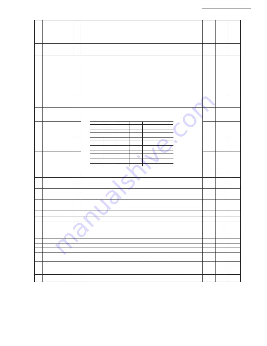
26 BIAS (H)
O
Linear Audio record timing terminal
When recording linear audio, take (H) as output
Output mode: REC,(ADUB,AV-INSERT)
When start recording, set BIAS(H), R.REC(H) output range 140~160msec
recording time
When finish recording, BIAS(L) = Output, D.REC(L) Time = 0 ~ 20 msec
Low
Low
Low
27 S.TAB (L)
I
SAFETY TAB DETECTION INPUT
WITH Safety Tab: Input = Low
Without Safety Tab: Input = High
In
In
In
28 FM MUTE (H)
O
Audio Mute Output terminal
During P.Off,Head cleaning,Timer Standby,and VPS/PDC Standby,
(After canceling these modes,take (L) as the output after delayed time= 600msec.
During VV,when tape speed is not 1 time speed, Output = High.
(Take (L) as the output, after switching over to 1 time speed,and after delayed
time = 600msec.
Take (H) as the output During switching over of EE/VV, Output = High after
interposing the changing point.
(Take (L) as the output, after switching over of EE/VV, and delayed time= 600ms.
When J.CLK/A.DEF/NOR terminal is A.DEF, Output = High.
High
Hi-z
High
29 SW1
O
AUDIO SYSTEM (TUNER PRESET) select terminal.
AUDIO SYSTEM = BG, I: High is Output
AUDIO SYSTEM = DK, M: Low is Output
Hi-Z
Hi-Z
Hi-Z
30 POS.SW4
I
In
In
In
31 POS.SW3
I
In
In
In
32 POS.SW2
I
In
In
In
33 POS.SW1
I
In
In
In
34 RESET (L)
I
Reset terminal
In
In
In
35 32KHz IN
I
Sub clock 32.768KHz osc.input
In
In
In
36 32KHz OUT
O Sub clock 32.768KHz osc.output
Out
Out
Out
37 5V (D)
-
Digital port Power Vcc (5V)
-
-
-
38 12MHz IN
I
Main clock 12/16MHz osc.input.
In
In
In
39 12MHz OUT
O Main clock 12/16MHz osc.output.
Out
Out
Out
40 GND (OSC)
-
OSC circuit Digital GND.
-
-
-
41 NC
Unused terminal. Fixed Output = Low
Low
Low
Low
42 NC
Unused terminal.Fixed Output = Low.
Low
Low
Low
43 32K.START (L)
I
Clock source selection terminal during reset start.
Connect Vcc(5V), when 12/16 MHz High speed mode
Connect to Vss(0V), when 32KHz low speed mode
In
In
In
44 LC.OSC IN
I
LC osc. Input terminal
In
In
In
45 LC.OSC OUT
O LC osc. Output terminal
Out
Out
Out
46 GND
-
Terminal B for testing. ( connected to GND )
-
-
-
47 4FC LPF
I
Internal OSC Connection terminal for sync generator circuit.
In
Low
In
48 FSC IN
I
Sub carrier (fsc) input terminal for sync generator circuit.
In
Low
In
49 GND (OSD)
-
GND terminal for OSD circuit
-
-
-
50 CV IN
I
Composite Video signal input terminal
In
In
In
51 KILLER (H)
I
KILLER/COLOR Detection Input Terminal.
KILLER : High COLOR : Low
In
In
In
52 CV OUT
O
Composite Video Signal Output Terminal.(Do not use as common port)
Out
Out
Out
Mecha position Input
Refer to the mecha timing chart for Input result data control.
POS.SW1
POS.SW2
POS.SW3
POS.SW4
Position
0
0
0
0
0
0
0
1
0
0
1
0
DOWN
0
0
1
1
R-REW
0
1
0
0
LOAD
0
1
0
1
REV
0
1
1
0
PLAY
0
1
1
1
POFF
1
0
0
0
STOP_R
1
0
0
1
STOP_F
1
0
1
0
1
0
1
1
1
1
0
0
FF / REW
1
1
0
1
1
1
1
0
EJECT
1
1
1
1
51
NV-VP60GL / NV-VP60GC / NV-VP60GCS
Содержание NV-VP60GC
Страница 8: ...6 GENERAL DESCRIPTION 6 1 OPERATING INSTRUCTIONS 8 NV VP60GL NV VP60GC NV VP60GCS ...
Страница 9: ...9 NV VP60GL NV VP60GC NV VP60GCS ...
Страница 31: ...4 Cut the antistatic flexible sheet for the optical pickup unit Fig 4 31 NV VP60GL NV VP60GC NV VP60GCS ...
Страница 37: ...37 NV VP60GL NV VP60GC NV VP60GCS ...
Страница 64: ...NV VP60GL NV VP60GC NV VP60GCS 64 ...
Страница 80: ...NV VP60GL NV VP60GC NV VP60GCS 80 ...
Страница 87: ...18 EXPLODED VIEWS 18 1 VCR MECHANISM CHASSIS PARTS SECTION 87 NV VP60GL NV VP60GC NV VP60GCS ...
Страница 88: ...18 2 DVD MECHANISM CHASSIS PARTS SECTION 88 NV VP60GL NV VP60GC NV VP60GCS ...
Страница 89: ...18 3 CASING PARTS SECTION 89 NV VP60GL NV VP60GC NV VP60GCS ...
Страница 90: ...18 4 PACKING PARTS SECTION 90 NV VP60GL NV VP60GC NV VP60GCS ...


