D
[RGB] means separate Red/Green/Blue colour signals. If you connect a TV equipped with RGB
input capability to the AV1 socket on this VCR, and a decoder equipped with RGB output
capability to the AV2 socket, RGB signals will pass through the VCR to the TV when the VCR is
in stand-by mode. The RGB signals cannot be recorded or produced by this VCR.
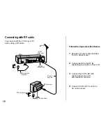
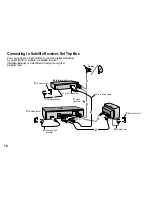
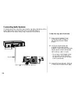
Connect a 21-pin scart cable (fully wired) to the AV2 21-pin scart socket on the
VCR and to the 21-pin scart socket on the External unit.
Connect a 21-pin scart cable (fully wired) to the AV1 21-pin scart socket on the
VCR and to the 21-pin scart socket on the TV set.
Connect the External unit, VCR and TV set to the AC mains supply.
Switch on the TV set and VCR.
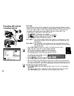
Set the VCR menu settings for AV2 according the connected External unit (See page 34).
Follow the steps described below.
2
3
5
Ensure TV Power, External unit Power and VCR Power are disconnected from
AC Mains socket.
1
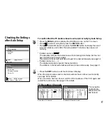
Switch on the External unit. Then follow page 13 for VCR Auto Setup with 21-pin
Scart cable.
6
15
Connect aerial to the Aerial in connector of the External unit.
Connect the External unit´s Aerial out connector to the VCR’s RF IN (Aerial input).
Connect the VCR´s RF OUT (Aerial output) to the TV set’s Aerial in connector.
4


