4.4. Door assembly
1. Open the door and remove door C from door E by carefully
pulling outward starting from upper right hand corner.
2. Remove door key and door key spring.
3. Remove 2 screws holding side frame of door A.
4. Seperate the door A from the door E by freeing catch hooks
on the door A using a flat screwdriver.
To re-install components:
NOTE:
After replacement of the defective component parts
of the door, reassemble it properly and adjustment
so as to prevent an excessive microwave leakage.
Adjustment of the door assembly (Refer page 11).
5. When mounting the door to the oven, be sure to adjust the
door parallel to the bottom line of the oven face plate by
moving the upper hinge and lower hinge in the direction
necessary for proper alignment.
6. Adjust so that the door has no play between the inner door
surface and oven front surface. If the door assembly is not
mounted properly, microwave power may leak from the
clearance between the door and oven.
NOTE:
Door alignment is crucial. If door is misaligned, apply
pressure until alignment is achieved.
NOTE:
Adjust so that the upper portion of the door will touch
firmly to the oven cavity front plate, without pushing the
door. If the door assembly is not mounted properly,
microwave power may leak from the clearance between
the door and oven.
Be sure the gap between door E and cavity front plate will be
0.3~0.8mm.
NOTE:
Always perform the microwave leakage measurement
test after installation and adjustment of door assembly.
4.5. Floor shelf and/or moving
antenna
1. Insert a phillips type screwdriver or equivalent approx. 2"
(5 cm) in shaft length in the access hole in the left side oven
wall as shown in Figure.
2. Carefully lift up the floor shelf by prying up with the
screwdriver until the floor shelf is lifted up over the level of
oven front opening.
3. Remove the floor shelf by lifting it out through the oven
front.
To replace moving antenna.
4. Remove the moving antenna by simply lifting it up off the
stirrer motor shaft.
NOTE:
When replacing the moving antenna, make sure the
plastic stirrer spacers are correctly in place. They
are necessary to stabilize the antenna by gliding
around the oven bottom as the antenna turns.
8
NE-1022F
Содержание NE-1022F
Страница 2: ...2 NE 1022F ...
Страница 4: ...1 CONTROL PANEL 4 NE 1022F ...
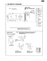
Страница 5: ...2 SCHEMATIC DIAGRAM 5 NE 1022F ...
Страница 13: ...7 4 At least once a year have the radiation monitor checked for calibration by its manufacturer 13 NE 1022F ...
Страница 15: ...8 1 How to check the semiconductors using an OHM meter 15 NE 1022F ...
Страница 16: ...9 EXPLODED VIEW AND PARTS LIST 9 1 EXPLODED VIEW 16 NE 1022F ...


