5.6. Diode
1. Isolate the diode from the circuit by disconnecting the leads.
2. With the ohmmeter set on the highest resistance scale,
measure the resistance across the diode terminals.
Reverse the meter leads and again observe the resistance
reading. Meter with 6V, 9V or higher voltage batteries
should be used to check the front-to-back resistance of the
diode, otherwise an infinite resistance may be read in both
directions.
A normal diode´s resistance will be infinite in one direction
and several hundred k
Ω
in the other direction.
5.7. Protector diode
1. Isolate the protector diode assembly from the circuit by
disconnecting its leads.
2. With the ohmmeter set on the highest resistance scale,
measure the resistance across the protector diode
terminals.
Reverse the meter leads and again observe the resistance
reading. A normal protector diode´s resistance will be
infinite in both directions.
It is faulty if it shows continuity in one or both directions.
10
NE-1022F
Содержание NE-1022F
Страница 2: ...2 NE 1022F ...
Страница 4: ...1 CONTROL PANEL 4 NE 1022F ...
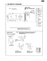
Страница 5: ...2 SCHEMATIC DIAGRAM 5 NE 1022F ...
Страница 13: ...7 4 At least once a year have the radiation monitor checked for calibration by its manufacturer 13 NE 1022F ...
Страница 15: ...8 1 How to check the semiconductors using an OHM meter 15 NE 1022F ...
Страница 16: ...9 EXPLODED VIEW AND PARTS LIST 9 1 EXPLODED VIEW 16 NE 1022F ...


