- 7 -
NC-BH30P, BH40P
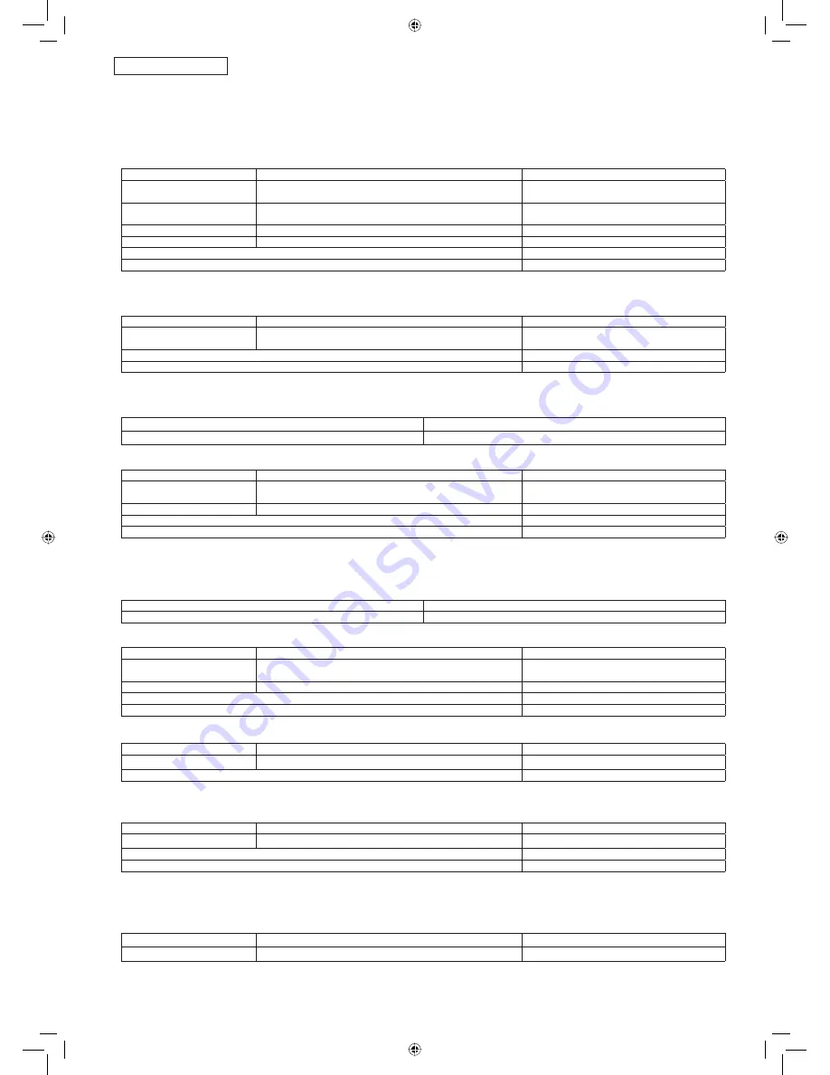
2.3. Failure Diagnostics Chart
2.3.1. No power. (There is no power indication.)
➞
Sections 2.4.1 to 2.4.7
describe electric power supply.
The items in the “Check” column correspond to those shown in Check Points on P.6.
Check
Diagnostics Method
Action
Thermal fuse comp.
Is there connection between the white lead wire on the peg
frame and the CN3 connector of the control unit A? (0
Ω
)
Replace the thermal fuse comp.
Keep warm heater
Is there connection across the boiling heater contacts?
(approx. 133
Ω
)
The container comp.
Power cord
Is there connection in the power cord? (0
Ω
)
Replace the power cord.
Lead wire assy. E comp.
Is there connection in the lead wire assy. E? (0
Ω
)
Replace the lead wire assy. E.
When the above parts are normal
Replace the control unit A (bottom)
When the above parts are normal
Replace the control unit B (operation)
2.3.2. Water is not boiling. (Water comes out.)
The items in the “Check” column correspond to those shown in Check Points on P.6.
Check
Diagnostics Method
Action
Water Heater
Is there connection between the white lead wire and
the red lead wire? (approx.14
Ω
)
Replace the container comp.
When the above parts are normal
Replace the control unit A (bottom)
When the above parts are normal
Replace the control unit B (operation)
2.3.3. Water does not come out, or water
fl
ow is restricted. (Water is boiling.)
Check point
Diagnostics Method
Action
Is the
fi
lter (located at the bottom of container) clogged?
Clean or replace the
fi
lter.
The items in the “Check” column correspond to those shown in Check Points on P.6.
Check
Diagnostics Method
Action
Electric pump
Turn on the 100V power, and press the Lock/Unlock pad
fi
rst
and then the Pour out pad. Is the motor heard running?
Replace the electric pump.
Lead wire assy. E comp.
Is there a miss-connection in the lead wire assy. E (0
Ω
)
Replace the lead wire assy. E.
When the above parts are normal
Replace the control unit B (bottom)
When the above parts are normal
Replace the control unit A (operation)
2.3.4. Reboil and Vacuum Keep Warm lamps illuminate alternately.
(Overheating protection mode/Bottom thermistor disconnection comp. mode)
Check point
Diagnostics Method
Action
Is there water inside?
Supply water and press Reboil pad.
The items in the “Check” column correspond to those shown in Check Points on P.6.
Check
Diagnostics Method
Action
Thermistor comp.
Is there connection between blue lead wire and blue
lead wire? (approx.45
Ω
at approx. 20°C)
Replace the thermistor comp.
Lead wire E comp.
Is there connection in the lead wire assy. E? (0
Ω
)
Replace lead wire E comp.
When the above parts are normal
Replace the control unit B (bottom)
When the above parts are normal
Replace the control unit A (operation)
2.3.5. The Select pad does not work
Check
Diagnostics Method
Action
–
–
Replace the control unit B (bottom)
When the above parts are normal
Replace the control unit A (operation)
2.3.6. The Lock/Unlock pad does not work.
The items in the “Check” column correspond to those shown in Check Points on P.6.
Check
Diagnostics Method
Action
Lead wire E comp.
Is there miss-connection in the lead wire assy E? (0
Ω
)
Replace lead wire E comp.
When the above parts are normal
Replace the control unit B (bottom)
When the above parts are normal
Replace the control unit A (operation)
2.3.7. Hot water does not dispense smoothly.
(Immediately after being boiled in particular) Boiling is too noisy.
Scale accumulation becomes severe inside the container.
Check
Diagnostics Method
Action
–
–
Clean with citric acid
NC-BH40-30-22.indd 7
NC-BH40-30-22.indd 7
14-08-07 16:47:59
14-08-07 16:47:59


