background image


14


  START-UP OF UNIT


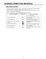
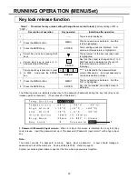
Follow the procedures for the initial and consequent operations of the unit. 

 
1.

 Connect the power cord to the dedicated outlet having appropriate rating with the chamber empty, and 

turn on the power switch on the freezer. 
 

2.

 Turn off the switch of the backup cooling kit    (optional component) if it is installed. 

 
3.

 Turn on the battery switch.


4.

 The audible alarm may activated.    In this case, press the buzzer stop key (BUZZER) to silence the 

alarm. 
 

5.

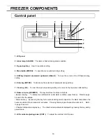
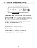
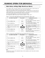
 Set the desired chamber temperature.    See page 18 for the temperature setting. 


6.

 Check that the chamber temperature reaches the desired temperature. 

 
7.

 Turn on the switch of backup cooling kit    (optional component) if it is installed. 


8.

 Check that the alarm lamp blinks and the buzzer sounds by pressing the alarm test key. 


9. 

After confirming the above, you can put articles into the chamber in a small batch to prevent the 

temperature rise. 


CAUTION


Do not put too many warm articles in the chamber.    The temperature rise may cause the damage to 
the articles in the chamber.


Operation after power failure 


The set value is memorized by nonvolatile memory.   Accordingly, the chamber resumes the operation 
with setting before power failure.    During the power failure, the clock function is operating. 
 

WARNING


When this product operates at the first start-up or after no use for long period, the built-in battery capacity 
may be lowered or completely zero because of discharge of the battery.    After installation the product, 
the freezer should operate for more than 3 days (72 hours) to charge the battery. 


Содержание MDF-U700VX-PB

Страница 1: ...ns carefully before using this product and save this operating instructions for future use See page 54 for all Model Numbers MDF U700VX MDF U700VXC Series MDF U700VX MDF U700VXC Ultra Low Temperature Freezer Operating Instructions ...

Страница 2: ... MENU Tools P 27 Initialization Tools Default Setting P 27 Set of date time log interval Tools Date Time P 28 Set of door alarm delay time Tools Door Delay P 29 Set of log interval Tools Log Interval P 30 Change of compressor delay time Tools Comp Delay P 31 Set of key lock password Tools Key Lock PW Setting P 32 ALALRM BUZZER P 32 MONITOR OF FREEZER STATUS P 33 ALARMS SAFETY FUNCTIONS P 34 ROUTIN...

Страница 3: ...nce or functions Contact our sales representative or agent if any page of the operating instructions is lost or page order is incorrect Contact our sales representative or agent if any point in this operating instructions is unclear or if there are any inaccuracies No part of this operating instructions may be reproduced in any form without the expressed written permission of our company CAUTION O...

Страница 4: ...on must be followed Be sure to keep this operating instructions in a place accessible to users of this unit Some warning and or caution labels are attached on the unit Following shows the description of such labels This label is on the cover in which the electrical components of high voltage are enclosed to prevent the electric shock The cover should be removed by a qualified engineer or a service...

Страница 5: ...ower supply outlet is not grounded it will be necessary to install a ground by qualified engineers Never ground the unit through a gas pipe water main telephone line or lightning rod Such grounding may cause electric shock in the case of an incomplete circuit Connect the unit to a power source as indicated on the rating label attached to the unit Use of any other voltage or frequency other than th...

Страница 6: ...n Disconnect the power supply plug if there is something wrong with the unit Continued abnormal operation may cause electric shock or fire When removing the plug from the power supply outlet grip the power supply plug not the cord Pulling the cord may result in electric shock or fire by short circuit Disconnect the power supply plug before moving the unit Take care not to damage the power cord A d...

Страница 7: ... insertion may cause a heat or ignition Never store corrosive substances such as acid or alkali in this unit if the cylinder cannot be sealed These may cause corrosion of inner components or electric parts Check the setting when starting up of operation after power failure or turning off of power switch The stored items may be damaged due to the change of setting Be careful not to tip over the uni...

Страница 8: ... 40 o C Maximum relative humidity 80 for temperature up to 31 o C decreasing linearly to 50 relative humidity at 40 o C Mains supply voltage fluctuations up to 10 of the nominal voltage Transient overvoltages up to the levels of OVERVOLTAGE CATEGORY II Temporary OVERVOLTAGES occurring on the mains supply Applicable pollution degree of the intended environment POLUTION DEGREE 2 in most cases ...

Страница 9: ...8 FREEZER COMPONENTS Rear side A compressor B compressor 16 17 15 4 1 3 5 6 8 11 7 9 10 12 13 2 14 POWER 7 ...

Страница 10: ... Keep the unit in level at the installation 10 Caster 4 casters are provided to facilitate moving of the cabinet For the installation adjust the leveling feet so that the front 2 casters cannot contact with the floor 11 Space for temperature recorder A temperature recorder optional component can be attached here See page 45 Temperature recorder Option 12 Lock Turn clockwise to 180 o with a key and...

Страница 11: ...to return to the top screen after setting 8 Buzzer stop key BUZZER This key has three functions as follows Buzzer stop key To silence the audible alarm under alarm condition press this key Refer to page 34 and 35 for the details Alarm test key By pressing this key for 5 seconds during normal operation the alarm lamp blinks the buzzer sound and the remote alarm activates Pressing this key again fin...

Страница 12: ...and this is because air inside the chamber contracted When a door is closed and opened soon a door is easy to open with the following process 1 Turn the cap of the left side counterclockwise about two laps That can be removed completely 2 Put the air into the chamber from about twenty seconds and open a door 3 Close a cap if a door opens A door may not open in the above method when there are frost...

Страница 13: ...y cause vibration or noise WARNING Install the unit on a sturdy floor If the floor is not strong enough or the installation site is not adequate this may result in injury from the unit falling or tipping over Select a level and sturdy floor for installation This precaution will prevent the unit from tipping Improper installation may result in water spillage or injury from the unit tipping over A l...

Страница 14: ...veling foot Extend the leveling feet by rotating them counterclockwise to contact them to the floor Ensure the unit is level Fig 1 3 Fix the unit Two fixtures are attached to the rear of the frame Fix the frame to the wall with these fixtures and rope or chain Fig 2 WARNING Use a power supply outlet with ground earth to prevent electric shock If the power supply outlet is not grounded it is necess...

Страница 15: ...f it is installed 8 Check that the alarm lamp blinks and the buzzer sounds by pressing the alarm test key 9 After confirming the above you can put articles into the chamber in a small batch to prevent the temperature rise CAUTION Do not put too many warm articles in the chamber The temperature rise may cause the damage to the articles in the chamber Operation after power failure The set value is m...

Страница 16: ...zer Ring Back 30 min Default setting Setting range 0 1 99 min Refer to page 21 1 6 Key lock Key Lock 0 Default setting 0 Unlock 1 Lock Refer to page 22 23 2 Log Log When this function is used an optional interface board is necessary Contact our sales representative or agent at the time of installation of the optional parts 2 1 Log data on past the first PC 1D Refer to page 24 2 2 All of the log da...

Страница 17: ...h page 35 3 Display of status Status Stand by is usually displayed A status number is displayed and an additional message is displayed in the message column when the operation monitor system detects the specified status Refer to page 33 for the operation monitor system 4 Display of door status Door Closed is displayed when the door is close Open is displayed When the door is open 5 Display of date...

Страница 18: ... temperature alarm Temperature settable range between chamber temperature 5 and 40 o C The factory setting is chamber temperature 10 o C 4 Alarm Delay This is a setting of delay time of alarm buzzer for high and low temperature alarm The settable range is between 0 and 15 minutes When 0 is set the alarm buzzer sound without delay The factory setting is 15 minutes 5 Ring Back This is the duration b...

Страница 19: ...ayed 2 Press the MENU button MENU The menu window is indicated And the set is highlighted 3 Press the ENTER key ENTER Temp Setting window indicated And set value of temperature is highlighted 4 Figure input key is pressed in order of 7 5 Chamber temperature is changed from 80 to 75 5 Press the MENU button MENU The menu window is indicated And the OK is highlighted 6 Press the ENTER key ENTER Chamb...

Страница 20: ...m by pressing Shift keys The set value 10 of the high temperature alarm High Alarm is highlighted 5 Figure input key is pressed in order of 0 5 High temperature alarm is changed from 10 to 5 6 Press the MENU button MENU The menu window is indicated And the OK is highlighted 7 Press the ENTER key ENTER High temperature alarm is memorized and the top screen is indicated Table 3 Procedure for setting...

Страница 21: ...isplayed 2 Press the MENU button MENU The menu window is indicated And the set is highlighted 3 Press the ENTER key ENTER Temp setting window indicated And set value of temperature is highlighted 4 Select Alarm Delay by pressing Shift keys The set value 15 of the alarm delay time Alarm Delay is highlighted 5 Figure input key is pressed in order of 1 0 Alarm delay time ALARM Delay is changed from 1...

Страница 22: ...perature is highlighted 4 Select Ring Back by pressing Shift keys The set value 30 of the ring back time Ring Back is highlighted 5 Figure input key is pressed in order of 1 0 Ring back time Ring Back is changed from 30 to 10 6 Press the MENU button MENU The menu window is indicated And the OK is highlighted 7 Press the ENTER key ENTER Ring back time is memorized and the top screen is indicated No...

Страница 23: ...to Lock Description of operation Key operated Indication after operation 1 Top screen is displayed 2 Press the MENU button MENU The menu window is indicated And the set is highlighted 3 Press the ENTER key ENTER Temp setting window indicated And set value of temperature is highlighted 4 Select Key lock by pressing Shift keys The set value 0 of the key lock Key Lock is highlighted 5 Figure input ke...

Страница 24: ...s pressed in order to 0000 And press the ENTER key is indicated in the password input column Password An input password is not indicated with a number 7 Press the MENU button MENU The menu window is indicated And the OK is highlighted 8 Press the ENTER key ENTER Key lock is canceled and a top screen is indicated The following screen is indicated when input of a password Password during the key loc...

Страница 25: ...e start Start of the menu window and press the ENTER key ENTER Transmission is started in the personal computer of the log data on chamber temperature of 1 day being recorded Sending and the number of transmit data are indicated in the display at the time of the transmission 8 A completion message Finished is indicated The end of the log data display 9 If a completion message is indicated press th...

Страница 26: ...he display 8 A completion message Finished is indicated The end of the log data display 9 If a completion message is indicated press the MENU button MENU The menu window is indicated And the Start is highlighted 10 A shift key is pressed and Cancel of the menu window is chosen and press the ENTER key ENTER Log data on 1 day of chamber temperature are indicated by the graph in the display 11 Press ...

Страница 27: ...etup of the connection Connecting port COM1 Properties of COM1 Setup of the port Bit sec 9600 Data bit 8 Parity No Stop bit 1 Flow control Xon Xoff When a log transmitting screen is opened terms of communication on the MDF side are set on the above condition automatically 3 Data transmitting screen is displayed Specify a transfer a capture of the textbook and a preservation file name by the operat...

Страница 28: ...mmunication speed when it is connected with the DAQ system and so on It can be set up in 0 2400bps 1 4800bps and 2 9600bps Though a display screen is the indication of 0 and 2 But it can be set in 1 Usually set up 0 2400bps It is the DAQ standard command mode Factory setting is 0 2400bps 3 DAQ ID Select any ID between 1 and 250 when an optional interface beard is attached At this time never overla...

Страница 29: ... range is between 3 minutes until 15 minutes Factory setting is 3 minutes Table 10 Setting of date and time When time is set up at 12 00 00 on December 1 2010 Description of operation Key operated Indication after operation 1 Top screen is displayed 2 Press the MENU button MENU The menu window is indicated And the set is highlighted 3 Press the shift key highlight the Tools menu window and press t...

Страница 30: ...ted And the set is highlighted 3 Press the shift key highlight the Tools menu window and press the ENTER key Select Tools window is indicated 4 Press the shift key highlight the Date Time and press the ENTER key The Date is highlighted 5 Select Door Delay by pressing MENU button Then pressing ENTER key Door Delay setting window is indicated 6 Figure input key is pressed in order of 1 0 The numeric...

Страница 31: ...e set is highlighted 3 Press the shift key highlight the Tools menu window and press the ENTER key Select Tools window is indicated 4 Press the shift key highlight the Date Time by pressing ENTER keys The Date is highlighted 5 Select Log Interval by pressing MENU button Then pressing ENTER key Log Interval setting window is indicated 6 Figure input key is pressed in order of 1 0 Log Interval is ch...

Страница 32: ...r operation 1 Top screen is displayed 2 Press the MENU button MENU The menu window is indicated And the set is highlighted 3 Press the shift key highlight the Tools menu window and press the ENTER key Select Tools window is indicated 4 Press the shift key highlight the Date Time by pressing ENTER keys The Date is highlighted 5 Select Comp Delay by pressing MENU button Then pressing ENTER key Comp ...

Страница 33: ...with the intermittent tone if it is the condition that the door opens beyond the time when it is set up with door delay It stops if a door is closed Filter alarm buzzer intermittent tone It is informed with the intermittent tone when the temperature of filter sensor is beyond 48 0 o C Buzzer sound stops when the temperature of the filter sensor is less than 43 0 o C Buzzer stops if the buzzer stop...

Страница 34: ...ply outlet or degrade of starting performance of refrigerating circuit Use dedicated power source The notice of the overload operation When it did not reach setup temperature for more than 5 days STATUS indication Status_3 is indicated Message indication Cooling circuits Overload is indicated A problem occurs in the cooling performance and the durability of the cooling circuit 1 Large quantities o...

Страница 35: ...n during the power failure The memory of the set point before the power failure The set value is memorized by nonvolatile memory The freezer resumes the operation with setting before power failure Key lock When the key lock is on Setup cannot be changed Auto return When there is no key pressing in each setting mode for 90 seconds Chamber temperature is displayed Finishing of each setting mode Batt...

Страница 36: ...Error E16 Fan motor A abnormal Intermittent tone Remote alarm Fan motor B is continuous running If the fan motor B is stopped Message indication Error E17 Fan motor B abnormal Intermittent tone Remote alarm Fan motor A is continuous running Cooling circuit abnormality If the cooling circuit A broke down Message indication Error E18 Cooling circuit A abnormal Intermittent tone Remote alarm If the c...

Страница 37: ...p cooling kit by pressing test switch once a month if it is installed Remove the frost or ice on the chamber wall and clean the condenser filter once a month Defrosting of inside wall The frost is built at the upper portion of the chamber and inner door The excessive frost possibly make some gap between the cabinet and door gasket which may cause poor cooling Remove the frost on the inner door wit...

Страница 38: ...ort The pipe of the air intake port is thrust with a stick for air intake port cleaning of the accessories and frost is taken An outer door does not open even if the cap of the air intake port is opened The pipe of the air intake port is thrust with a stick for air intake port cleaning of the accessories and frost is taken Frost and ice can be seen in the chamber Frost inside the chamber and ice a...

Страница 39: ...sed completely The outer door is not closed firmly The frost or ice between the cabinet and door gasket possibly prevents door seal The air intake vent is blocked The door is not shut tightly The inner door is not installed correctly The set temperature in the controller is not set properly The grille is blocked out The freezer is in the direct sunlight There is any heating source near the freezer...

Страница 40: ...doors to prevent accidents such as suffocation Recycle of battery The unit contains a rechargeable battery The battery is recyclable At the end of it s useful life check with you local solid officials option or proper disposal Label indication is obliged to comply with Taiwanese battery regulation Decontamination of unit Before disposing a ultra low temperature freezer with biohazardous danger dec...

Страница 41: ...spose of them correctly at your local community waste collection recycling centre Please help us to conserve the environment we live in German Für EU Staaten Das Symbol und das erwähnte Wiederverwertungssystem gelten nur für die Länder der EU und nicht für andere Länder oder Gebiete in der Welt Die Produkte von Panasonic werden aus hochwertigen Materialien und Komponenten gefertigt die sich wieder...

Страница 42: ...u éliminées de manière inappropriée peuvent s avérer potentiellement dangereuses pour la santé humaine et pour l environnement Cependant ces matières sont nécessaires au bon fonctionnement de votre appareil ou de votre machine Pour cette raison il vous est demandé de ne pas vous débarrasser de votre appareil ou machine usagé avec vos ordures ménagères Spanish PARA USUARIOS DE LA UNION EUROPEA El s...

Страница 43: ...em recolha de lixo local Por favor ajude nos a conservar o ambiente Italian PER UTENTI UE Il simbolo e i sistemi di riciclaggio descritti di seguito si applicano esclusivamente ai paesi dell UE Questo prodotto Panasonic è stato progettato e realizzato con materiali e componenti di elevata qualità che possono essere riciclati e o riutilizzati Il simbolo di riciclaggio mostrato di seguito indica che...

Страница 44: ...bij uw plaatselijk afvalinzameling recyclingcentrum in uw buurt Help ons het milieu waarin wij leven in stand te houden Swedish FÖR ANVÄNDARE INOM EU Den symbolmärkning och de återvinningssystem som beskrivs här nedan gäller länder inom EU och gäller inte länder i någon annan del av världen Din Panasonic produkt har konstruerats och tillverkats med delar och material av hög kvalitet som kan återvi...

Страница 45: ...f nickel metal hydride battery 1 Turn off the power switch and disconnect the power supply plug 2 As shown in the Fig 2 remove 6 screws fixing the side panel with a screw driver and remove the side cover 3 Remove 4 screws fixing the electrical box panel with a screw driver Fig 2 4 Remove 2 screws fixing the battery mounting plate Fig 3 Disconnect the battery connector Fig 4 5 Take out the battery ...

Страница 46: ... the pen point is apart from the recording paper 2 Pull the cartridge out of the mounted position as shown in Fig 1 and Fig 2 3 Set a new recording paper in place on the rear bottom of the cartridge Set the hole on the chart in the cog of the recording paper driving assembly and feed the recording paper in the direction of the arrow by driving the cog wheel Fig 3 4 Adjust the recording paper prope...

Страница 47: ...e case cover of battery at the left bottom Fig 3 Set a battery in the case with its minus pole positioned backward 4 Close the case cover and replace the cartridge 5 Lift up the pen holder lever and close the cover Setting of ink pen 1 Open the cover and let down the pen holder lever With this operation the pen point is apart from the recording paper 2 Pull the cartridge out of the mounted positio...

Страница 48: ... fit into the guide holes on the pen arm See to Fig 2 illustration 2 5 Press the two sides of the head clamp as indicated by the arrows to secure the ink pen See to Fig 2 illustration 3 From the side view the cartridge should fit perfectly on the arm Confirm that the pen arm is attached to both sides of the ink pen 6 After loading the ink pen return the pen lifter to the original position Confirm ...

Страница 49: ...to 32 days The center of the recording paper is divided into 32 equal sections The lines extending from these lines serve as the 32 day time scale Fig 4 Stopping recording 1 Turn OFF the power switch 2 When recording is stopped for a prescribed period place the caps back on the ink pen to prevent the ink from evaporating Replacing the recording paper 1 Slightly raise the end of the pen lifter and ...

Страница 50: ... OPTION Chamber temperature is the time when 70 o C can be holding for Liquid CO2 backup cooling kit Keep a liquefied CO2 cylinder at less than 31 o C The above data is the experiment value which uses liquid CO2 30L no load ...

Страница 51: ...er 1 Switch of backup cooling kit BACKUP When turning on the backup cooling kit the lamp is brightened This means that the backup cooling kit is ready To stop the operation of the backup cooling kit turn off this switch 2 Test switch TEST This switch is for checking the operation of backup cooling kit Pressing this switch is resulted in the release of liquid carbon dioxide without backup cooling k...

Страница 52: ...mance 82 o C at the center of the chamber ambient temperature 30 o C no load An optional inventory rack IR 224U cannot be used when an small inner door is installed INTERFACE BOARD OPTION Installation of MTR 480 MTR L03 Contact our sales representative or agent for the installation of a interface board Note When a data transmitting function to the personal computer is done an interface board MTR 4...

Страница 53: ...shelf stopper and shelves securely And store the inventory racks securely Incomplete installation may cause injury or damage NOTE Only inventory rack IR 220U can be applied when the small inner door MDF 7ID is installed Shelf support Shelf stopper No 3 under fifth screw from the top There is a mark which hollowed at the shelf support front side No 3 under second screw from the bottom There is a ma...

Страница 54: ...ower failure alarm Door alarm Sensor abnormality Fan motor abnormality Compressor temp abnormality Cooling circuit abnormality Remote alarm contact Allowable contact capacity DC 30 V 2 A Battery Nickel metal hydride battery DC 6 V 1100 mAh Auto recharge 5HR AAC Weight 375 kg 383 kg Voltage booster None Built in Optional component Temperature recorder MTR G85C Temperature recorder Recorder fixing M...

Страница 55: ...e level 53 dB A background noise 20 dB Maximum pressure 3041 kPa Note Specifications will be subject to change without notice The unit with CE mark complies with EC directives Product name Ultra Low Temperature Freezer MDF U700VXC Model No MDF U700VXC PA Cooling performance 86 o C at the center of the chamber ambient temperature 30 o C no load Temperature control range 50 o C to 86 o C ambient tem...

Страница 56: ...es 2 Contamination of the unit Unit interior Yes No No contamination Yes No Decontaminated Yes No Contaminated Yes No Others 3 Instructions for safe repair maintenance of the unit a The unit is safe to work on Yes No b There is some danger see below Yes No Procedure to be adhered to in order to reduce safety risk indicated in b below Date Signature Address Division Telephone Product name Model Ser...

Страница 57: ...Printed in Japan 7FB6P151578002 S0412 20612 1 1 1 Sakata Oizumi Machi Ora Gun Gunma 370 0596 Japan Panasonic Healthcare Co Ltd 2012 ...

Отзывы: