INSTRUCTION MANUAL
Collimated Beam Sensor
LA-A1 / LA-A1P
CMJE-LAA1 (06)No.0042-36V
Thank you very much for purchasing Panasonic products. Read this Instruction Man-
ual carefully and thoroughly for the correct and optimum use of this product. Kindly
keep this manual in a convenient place for quick reference.
WARNING
Never use this product as a device for personnel protection.
In case of using devices for personnel protection, use products which
meet laws and standards, such as OSHA, ANSI or IEC etc., for personnel
protection applicable in each region or country.
1
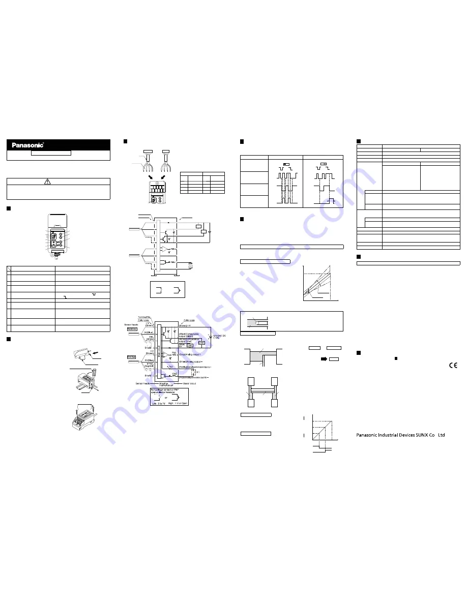
FUNCTION DESCRIPTION
POWER
STB
SPAN
SHIFT
ES
HIGH
LOW
LA-A1
1
2
3
4
5
6
7
10
8
9
Description
Function
1 Power indicator (Green
㧕
Lights up when the power is supplied.
2 Stability indicators(Green×3)
Light up in three steps in proportion to the
intensity of received
beam.
3 HIGH operation indicator(Orange)
Lights up when HIGH output is ON.
4
External synchronization
indicator (Green)
Lights up when the external synchronization
input is LOW.(Active-LOW)
5
External synchronization
selection switch
Selects between gate trigger(
) / or edge
trigger(
)
6 LOW operation indicator(Orange)
Lights up when LOW output is ON.
7 Span adjuster
15-turn adjuster sets the span for the analog
output voltage.
8 Shift adjuster
15-turn adjuster sets the offset for the analog
output voltage. It calibrates the output
voltage at zero input.
9 HIGH level adjuster
15-turn adjuster sets the HIGH output
threshold level.(Over-dark level).
10 LOW level adjuster
15-turn adjuster sets the LOW output
threshold level.(Under-dark level).
2
MOUNTING
Mounting on DIN rail
1.
Make sure the mounting stopper is
latched inside. Hook the front side
of the controller on the 35mm width
DIN rail at the bottom.
2.
Snap the controller down on the
35mm width DIN rail.
* -
driver into the mounting stopper
and pull out.
Stopper
1
35mm width
DIN rail
2
Flathead screwdriver
Stopper
Mounting with screws
Use two M4 screws that are com-
mercially
available. The tightening
torque should be 1.2N
㨯
m or less.
M4 pan head
screws
Please arrange
separately.
3
CONNECTION
Wiring diagram
Receiver
Emitter
Cable
Color code
Lower terminal block
for the emitter
Upper terminal block
for the receiver
Brown
White
Blue
Shield
Brown
Blue
Shield
STB
SPAN
SHIFT
1
2
3
4
5
6
7
8
9
POWER
LA-A1
6
7
8
9
2
3
4
5
Orange / V
iolet
Connect color-coded wires in accordance
with the table below.The receiver wires
should be connected on the upper terminal
block and the emitter wires on the lower ter-
minal block.
'OKVVGT
4GEGKXGT
Terminal
No.
Color code
Terminal
No.
Color code
2
5JKGNF
6
5JKGNF
3
Orange / Violet
7
9JKVG
4
$NWG
8
$NWG
5
$TQYP
9
$TQYP
Note: Do not connect any wire to the terminal No.1
I/O circuit diagram
㧨
LA-A1
NPN
㧪
100mA max.
100mA max.
75
ǡ
9
8
7
6
5
4
3
2
Terminal No.
Color code
Color code
s
Receiver
Emitter
(Brown) +V
(Gray) Analog
(Pink) External synchronization input ES +
(Pink / Blue) External synchronization input ES
(Shield) Analog output
(Blue) 0V
0V (Blue)
0V (Blue)
SYNC.
Shield
Shield
Main circuit
㧗
㧙
Load
Load +
*1
Users' circuit
Amplifier internal
circuit
Sensor heads
Non-voltage contact or
NPN open-collector transistor
Low: 0 to 1V
High: +V or Open
or
*1
I/O circuit diagram
㧨
LA-A1P
PNP
㧪
*1
Note
1):
㧨
NPN
㧪
When ES + (pink) and ES - (pink / blue) are connected, both HIGH and LOW
comparative outputs are triggered in the mode selected by the external synchronization
selection switch.
2):
㧨
PNP
㧪
When ES (pink/blue) and ES (pink) are connected, both HIGH and
LOWcomparative outputs are triggered in the mode selected by the external synchronization
selection switch.
3):To disable external synchronization, set the external synchronization selection switch on
'Gate trigger' and short-circuit the external synchronization inputs (ES + and ES -).
! " # "" $#& " ; <
more and connect the shield wire of the along output to 0V (common input) of the device.
5):Insulate all unused wires individually to avoid mis-contact.
4
EXTERNAL SYNCHRONIZATION FUNCTION
The external synchronization input controls the timing or the effective
duration of the two comparative outputs. Either, edge, or, gate trigger is
selectable.
Gate trigger
Edge trigger
External synchronization
selection switch
ON
OFF
High
Low
ON
OFF
ON
OFF
High
Low
ON
OFF
Aprox
40ms
Sensing signal
External synchronization
input
Comparative outputs
㧔
HIGH,LOW
㧕
External synchronization input signal : LOW ... 0 to 1V, High ...+V or Open
Note: To disable external synchronization, set the external synchronization selection switch on 'Gate trigger' and short-
circuit the external synchronization inputs (ES+ and ES -).
5
ALIGNMENT
Beam alignment of sensor heads
Make sure that, at least, one stability indicator lights up when you supply
LA-305
sensor heads. While aligning sensor
heads, the more stability indicators light up, the more reliable detection can be
obtained.
If either sensor head moves out of position, do all adjustments, including beam
alignment, from the beginning.
Refer to the instruction manual of
LA-305
for more details of beam alignment of sensor heads
Calibrating analog output
The analog voltage output relates to the span and the shift adjustments as in
How to calibrate the output into 1 to 5V
1.
Block the whole beam to enter into the
darkest condition and set the output at
1V with the shift adjuster.
2.
Allow the whole beam to be received to
enter into the lightest condition and set
the output at 5V with the span adjuster.
3.
For more accurate calibration, repeat
1
and
2
.
5V
1V
Span
adjustment
Shift
adjustment
Darkest
condition
Lightest
condition
Incident
beam
intensity
Analog output
㧨
Explanation
㧪
(e.g.) Wire detection
A
Wire
Collimated beam
B
C
Incident beam width = A + C
Interrupted beam width = B
Lightest condition: The entire beam is received.
Darkest condition: The entire beam is blocked.
Further use of shift adjuster
If you want to change the output voltage value after the calibration, the shift
adjuster enables you to shift the analog voltage up or down within about ±0.5V.
(e.g.) To shift the analog voltage from 2.51V to 3V with a certain amount of beam blockage
ޕ
Collimated beam
Sensing object
Emitter
Receiver
Darkest condition
Setting condition
Lightest condition
Previous
1V
to
2.51V
to
5V
Subsequent
1.49V
to
3V
to
5.49V
(Application) When two sensor heads are used for width measurement the shift adjuster can
eliminate the need to move the sensor heads during set-up.
Reference width
Collimated
beam
Collimated
beam
Sensing object
Emitter
Receiver
Emitter
Receiver
Up to now, the sensor heads have had to be located
at the exact positions with respect to the reference
object to measure at the criterion of 3V, center of 1
to 5V. However, even a simulated center is easily
obtained by the shift adjustment, without any
realignment
.
Note: To make the whole beam balanced between the lightest
and darkest conditions, the sensor heads should be posi-
tioned where the sensor generates 3V with the beam half
blocked.
Adjusting HIGH & LOW output levels (Two independent outputs)
HIGH output threshold level
Block as much of the beam for which you want
the HIGH output. Turn the HIGH adjuster to just
before the point where the HIGH operation indi-
cator lights up. The threshold level increases as
the adjuster is turned clockwise.
LOW output threshold level
Again, block as little of the beam for which you
want the LOW output. Turn the LOW adjuster to
just before the point where the LOW operation
indicator lights up. The threshold level increases
as the adjuster is turned clockwise.
$?!@QYZQ[\]#^_
LOW
output
level
HIGH
output
level
ON
OFF
ON
OFF
Darkest
condition
Lightest
condition
Incident
beam
intensity
Comparative
output (HIGH)
Comparative
output (LOW)
High
Low
Analog voltage
6
MAJOR SPECIFICATIONS
Designation
`^
㨯
Model No.
LA-A1
LA-A1P
Applicable sensor head
LA305
㧔
Note
)
Supply voltage
12 to 24V DC±10% Ripple P-P 10% or less
Current consumption
120mA or less (including sensor heads)
Comparative outputs
(HIGH,LOW)
NPN open-collector transistor
PNP open-collector transistor
・
Maximum sink current: 100mA
・
Applied voltage: 30V DC or less
(between comparative output
and 0V)
・
Residual voltage: 1.5V or less
(at 100mA sink cur-
rent)
0.5V or less
(at 16mA sink cur-
rent)
・
Maximum sink current: 100mA
・
Applied voltage: 30V DC or less
・
Residual voltage: 1.5V or less
(at 100mA source cur-
rent)
0.5V or less
(at 16mA source cur-
rent)
Response time
0.5ms or less
Output
operation
HIGH OUT: ON when the received beam level is equal or lower than
Over-dark level
LOW OUT: ON when the received beam level is equal or higher than
Under-dark level
Short-circuit
protection
Incorporated
Analog output
Analog voltage
・
Output voltage: 1V (Darkest) to 5V (Lightest)
・
\""!
Slew rate
8V/ms or more
Temperature
characteristics
0.05%F.S./
͠
or less
Ambient temperature
0 to +50
͠
(No dew condensation), Storage: -20 to +70
͠
Ambient humidity
35 to 85% RH, Storage: 35 to 85% RH
Material
Enclosure: Heat-resistant ABS, Terminal cover: Heat-resistant
ABS
Front cover: Polycarbonate
Cable
0.22mm
2
(Shield wire:0.15mm
2
) 7-core composite cabtyre, 2m long
Accessory
Adjusting screwdriver: 1 pc.
Note: Refer to the instruction manual of LA-305 for more details.
7
CAUTIONS
Make sure to use the exclusive sensor head
LA-305
&#_
This product has been developed / produced for industrial use only.
Make sure that the power supply is off while wiring.
Take care that wrong wiring will damage the sensor.
Verify that the supply voltage variation is within the rating.
If power is supplied from a commercial switching regulator, ensure that the
frame ground (F.G.) terminal of the power supply is connected to an actual
ground.
In case noise generating equipment (switching regulator, inverter motor,
etc.) is used in the vicinity of this product, connect the frame ground (F.G.)
terminal of the equipment to an actual ground.
Do not run the wires together with high-voltage lines or power lines or put
them in the same raceway. This can cause malfunction due to induction.
Extension up to total 50m, or less, is possible with 0.22mm
2
, or more,cable.
Use a shielded cable for extension of the analog output cable.
In case of using this product as a CE marking conformity product, cable
extension of the power wire and I/O wire must be wthin 30m.
! " #
the output until stabilized.
Make sure that stress by forcible bend or pulling is not applied directly to the
sensor cable joint.
This sensor is suitable for indoor use only.
Do not use this sensor in places having excessive vapor, dust, etc., or where it
may come in direct contact with water, or corrosive gas
Take care that the sensor does not come in direct contact with water, oil,
grease, organic solvents, such as, thinner etc., strong acid or alkaline.
Make sure to mount the terminal cover
8
INTENDED PRODUCTS FOR CE MARKING
The models listed under “
6
MAJOR SPECIFICATIONS
” come with
CE Marking. As for all other models, please contact us.
Contact for CE
Panasonic Marketing Europe GmbH Panasonic Testing Center
Winsbergring 15, 22525 Hamburg,Germany
Phone: 800.894.0412 - Fax: 888.723.4773 - Web: www.clrwtr.com - Email: [email protected]


