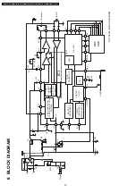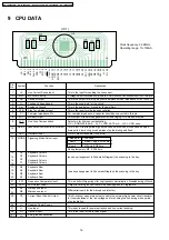
9 CPU DATA
(IC1)
Clock frequency: 3.58MHz
Operating range: 13~100mA
1
VSS
28
LS 1
MFL 2
RO 3
V
DD
4
A
GND
5
STB 6
CI 7
MO 8
LLC 9
V
SS
V
SS
HS/DP 10
OSC 11
MODE 12
C4 13
C3 14
C2 15
C1 16
R4 17
R3 18
R2 19
R1 20
FCI 21
LED 22
M1 23
M2 24
CS 25
V
SS
26
LI 27
RI 28
U4
U5
C1
C2 C3
C5 C4
C6
Pin
No.
Symbol
Function
1
2
3
4
5
6
7
8
9
10
11
12
13
14
LS
MFL
RO
V
DD
A
GND
STB
CI
MO
LLC
HS/DP
OSC
MODE
C4
C3
Line Current Sense Input
MF Level Setting
Receive Output
Positive Voltage Supply
Analogue Ground
Side Tone Balance Input
Complex Impedance Pin
Melody Output
Line Loss Compensation
Hook Switch Input and Dial Pulse Output
Oscillator Input
Signalling Mode Select Input
Keyboard Column
Keyboard Column
15
16
17
18
19
20
21
22
23
24
25
VSS
V
SS
EMC ground connection
26
27
28
C2
C1
R4
R3
R2
R1
FCI
LED
M1
M2
CS
V
SS
LI
RI
Keyboard Column
Keyboard Column
Keyboard Row
Keyboard Row
Keyboard Row
Keyboard Row
Frequency Comparator Input
LED Output Driver
Microphone Input
Microphone Input
Current Shunt Control Output
Negative Power Supply
Line Input
Receive Input
Description
This is the input for sending the line current.
A voltage divider connected from this pin to A GND and VSS can be used to set the DTMF level.
This is the output for driving a dynamic earpiece with an impedance of 140 to 300
This is the supply pin for the circuit.
This is the analog(ue) ground for the amplifiers.
This is the input for side tone cancellation.
For complex impedance a capacitor should be connected to this pin.
PDM output of the melody generator for tone ringing. Hi-Z when not active.
Select pin for line loss compensation.
LLC = AGND: 20-50 mA LLC = VDD: 45-75 mA LLC = VSS: none.
This is an I/O that is pulled high by the hook switch when off-hook and an open
drain pulls it low during break periods of pulse dialing and flash.
Pin for ceramic resonator (3.58 MHz).
Row 6 MF only, 82/82 ms
Mode pin
Function
Row 2
mode, 10 pps, 40/60 ms
During temporary MF : 82/160 ms
(see key arrangement in Schematic Diagram) the scanning to the key.
(see key arrangement in Schematic Diagram) the scanning to the key.
This is a Schmitt trigger input for ring frequency discrimination. Disabled during off-hook.
Output for driving an LED that will be flashing when in Programme.
Differential inputs for the microphone (electric).
This N-channel open drain output controls the external high power shunt transistor
for the modulation of the line voltage and for shorting the line during make period
of pulse dialing.
This input is used for power extraction and line current sending.
This is the input for the receive signal.
16
KX-TS2350CAB / KX-TS2350CAC / KX-TS2350CAH / KX-TS2350CAR / KX-TS2350CAW
Содержание KX-TS2350CAB
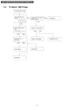
Страница 10: ...5 5 Problems With Ringer 10 KX TS2350CAB KX TS2350CAC KX TS2350CAH KX TS2350CAR KX TS2350CAW ...
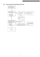
Страница 11: ...5 6 How to Check IC1 Scanning to the key 11 KX TS2350CAB KX TS2350CAC KX TS2350CAH KX TS2350CAR KX TS2350CAW ...
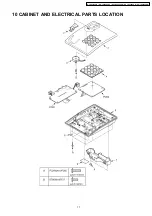
Страница 17: ...10 CABINET AND ELECTRICAL PARTS LOCATION 17 KX TS2350CAB KX TS2350CAC KX TS2350CAH KX TS2350CAR KX TS2350CAW ...
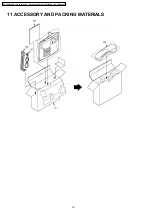
Страница 18: ...11 ACCESSORY AND PACKING MATERIALS 18 KX TS2350CAB KX TS2350CAC KX TS2350CAH KX TS2350CAR KX TS2350CAW ...
Страница 22: ...Memo 22 KX TS2350CAB KX TS2350CAC KX TS2350CAH KX TS2350CAR KX TS2350CAW ...
Страница 26: ...Memo 26 KX TS2350CAB KX TS2350CAC KX TS2350CAH KX TS2350CAR KX TS2350CAW ...

