83
KX-TG6700BXB/KX-TGA670BXB
12 Measurements and Adjustments
12.1. Things to Do after Replacing IC
12.1.1. X501 (Base Unit), X201 (Handset) Check
Equipment: Frequency counter
Check Point for measurement: BCK
Checking tolerance: 13.824 MHz ± 270 Hz (Base Unit)/13.824 MHz ± 100 Hz (Handset)
12.1.1.1. Check and Adjust X501 (Base Unit) Frequency
1. Set up Base Unit in TEST mode.
2. Press following keys in order to Adjust Crystal mode. [INTERCOM], [INTERCOM], [INTERCOM], [1], [4]. Check BCK
frequency.
3. If the BCK frequency is out of the checking tolerance (± 270 Hz), adjust to Adjustment tolelance (± 30 Hz) by pressing [ ] or
[ ] key.
Adjustment Tolerance: 13.824 MHz ± 30 Hz
4. Press [INTERCOM] key to write the new frequency factor in Memory.
5. Turn the power off. Then this value is available.
Cross Reference:
12.1.1.2. Check and Adjust X201 (Handset) Frequency
1. Set DC power supply to 2.6 V.
2. Set up Handset in TEST mode (Adjustment flow).
3. Press [1] key to Adjust Crystal mode (
“
Clock Adj.
”
is displayed on LCD). Check BCK frequency.
4. If the BCK frequency is out of the checking tolerance (± 100 Hz), adjust to Adjustment tolelance (± 30 Hz) by pressing [ ] or
[ ] key.
Adjustment Tolerance: 13.824 MHz ± 30 Hz
5. Press [TALK] key to write the new frequency factor in EEPROM.
6. Turn the power off. Then this value is available.
Cross Reference:
12.1.2. Adjust Battery Low Detector Voltage (Handset)
After Handset’s DSP (IC201) or EEPROM (IC241) replacement, Re-writing Battery Low voltage to EEPROM is required.
With following Handset Adjustment Flow, adjust DC power supply and DC voltmeter by the procedure below.
1. Set DC power supply to 2.6 V.
2. Set up Handset in TEST mode (Adjustment flow).
3. Press [1] key and [OFF] key to Adjust Batt Low mode. (“Bat Adj.” is displayed on LCD)
4. Change the voltage of the DC power supply to 2.34 V accurately. Check the voltage at P.C. board pads because some voltage
drops occur due to the usage of long or thin cables.
5. Press [TALK] key twice to write voltage value in EEPROM.
6. Press [TALK] key twice to write charge value 1 in EEPROM.
7. Change the voltage of the DC power supply to 2.90 V accurately.
8. Press [TALK] key twice to write charge value 2 in EEPROM.
9. Turn the power off. Then this value is available.
Note:
Refer to
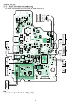
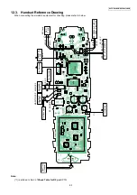
(P.85) for connection of DC power supply and voltmeter.
Cross Reference:
Содержание KX-TG6700BXB
Страница 2: ...2 KX TG6700BXB KX TGA670BXB ...
Страница 6: ...6 KX TG6700BXB KX TGA670BXB 3 Specifications ...
Страница 26: ...26 KX TG6700BXB KX TGA670BXB 4 8 2 Power Supply Circuit Voltage is supplied separately to each block ...
Страница 35: ...35 KX TG6700BXB KX TGA670BXB 4 11 Signal Route Each signal route is as follows ...
Страница 36: ...36 KX TG6700BXB KX TGA670BXB RF part signal route ...
Страница 37: ...37 KX TG6700BXB KX TGA670BXB 5 Location of Controls and Components 5 1 Controls 5 1 1 Base Unit ...
Страница 40: ...40 KX TG6700BXB KX TGA670BXB 6 1 2 Connecting the Telephone Line Cord ...
Страница 41: ...41 KX TG6700BXB KX TGA670BXB 6 1 2 1 If you subscribe to a DSL service ...
Страница 43: ...43 KX TG6700BXB KX TGA670BXB 6 4 1 Battery Level 6 4 2 Panasonic Battery Performance ...
Страница 44: ...44 KX TG6700BXB KX TGA670BXB 7 Operation Instructions 7 1 Symbols Used in These Operating Instructions ...
Страница 46: ...46 KX TG6700BXB KX TGA670BXB ...
Страница 47: ...47 KX TG6700BXB KX TGA670BXB 7 2 2 Programming Using the Direct Commands ...
Страница 48: ...48 KX TG6700BXB KX TGA670BXB ...
Страница 49: ...49 KX TG6700BXB KX TGA670BXB 7 3 Error Messages ...
Страница 50: ...50 KX TG6700BXB KX TGA670BXB 7 4 Troubleshooting ...
Страница 51: ...51 KX TG6700BXB KX TGA670BXB ...
Страница 52: ...52 KX TG6700BXB KX TGA670BXB ...
Страница 72: ...72 KX TG6700BXB KX TGA670BXB 10 1 9 5 RF DSP Interface Signal Wave Form Test Burst Mode ...
Страница 73: ...73 KX TG6700BXB KX TGA670BXB Test Burst Mode ...
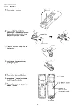
Страница 80: ...80 KX TG6700BXB KX TGA670BXB 11 1 2 Handset ...
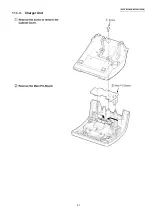
Страница 81: ...81 KX TG6700BXB KX TGA670BXB 11 1 3 Charger Unit ...
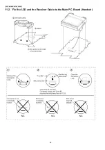
Страница 82: ...82 KX TG6700BXB KX TGA670BXB 11 2 Fix the LCD and the Receiver Guide to the Main P C Board Handset ...
Страница 93: ...93 KX TG6700BXB KX TGA670BXB Memo ...
Страница 97: ...97 KX TG6700BXB KX TGA670BXB Memo ...
Страница 106: ...106 KX TG6700BXB KX TGA670BXB Memo ...
Страница 116: ...116 KX TG6700BXB KX TGA670BXB 15 3 Explanation of IC Terminals RF Part 15 3 1 IC701 ...
Страница 117: ...117 KX TG6700BXB KX TGA670BXB 15 3 2 IC801 Backside Terminal GND ...
Страница 118: ...118 KX TG6700BXB KX TGA670BXB 15 3 3 IC851 Backside Terminal GND ...
Страница 119: ...119 KX TG6700BXB KX TGA670BXB 15 4 Terminal Guide of the ICs Transistors and Diodes 15 4 1 Base Unit 15 4 2 Handset ...
Страница 120: ...120 KX TG6700BXB KX TGA670BXB 16 Exploded View and Replacement Parts List 16 1 Cabinet and Electrical Parts Base Unit ...
Страница 122: ...122 KX TG6700BXB KX TGA670BXB 16 3 Cabinet and Electrical Parts Charger Unit ...
Страница 123: ...123 KX TG6700BXB KX TGA670BXB 16 4 Accessories and Packing Materials 16 4 1 KX TG6700BXB ...
Страница 124: ...124 KX TG6700BXB KX TGA670BXB 16 4 2 KX TGA670BXB ...


