background image

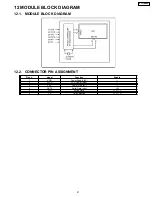
12 MODULE BLOCK DIAGRAM

12.1. MODULE BLOCK DIAGRAM

12.2. CONNECTOR PIN ASSIGNMENT

Pin no.

signal

Function

Enable

1

VDD

Power Supply (5V)

2

VLCD

LCD Power Input

3

VSS

Power Gnd (0V)

4

DATA

Serial Data Input

H/L

5

WR

Write Data

H, L

L

6

CS

Chip Selection

H, L

H

21

KX-T2375MXW

Содержание KX-T2375MXW

Страница 1: ...tric Co Ltd All rights reserved Unauthorized copying and distribution is a violation of law KX T2375MXW Integrated Telephone System White Version for Asia Middle Near East and other areas Telephone Equipment ORDER NO KM40108849C3 ...

Страница 2: ...S 18 10 BLOCK DIAGRAM 19 11 BLOCK DIAGRAM IC 1 20 11 1 Communication ICs 20 12 MODULE BLOCK DIAGRAM 21 12 1 MODULE BLOCK DIAGRAM 21 12 2 CONNECTOR PIN ASSIGNMENT 21 13 CIRCUIT OPERATION 22 13 1 Bell Detector Circuit 22 13 2 Line Interface 22 13 3 Speakerphone Circuit 23 13 4 Telephone Line Interface 24 13 5 Tone Detect 25 13 6 Inializing Circuit 26 14 TROUBLE SHOOTING GUIDE 27 14 1 Service Hints 2...

Страница 3: ...1 LOCATION OF CONTROLS 3 KX T2375MXW ...

Страница 4: ...2 DISPLAY 4 KX T2375MXW ...

Страница 5: ... device computer modem fax answering machine etc to the telephone line you can connect it through this unit using the DATA jack After connecting the handset and telephone line cord connect the communication device telephone line cord to the DATA jack Make sure the communication device is not in use before using this unit making calls storing phone numbers in memory etc or the communication device ...

Страница 6: ...de You can select the dialing mode by programming If you have touch tone service set to Tone If rotary or pulse service is used set to Pulse Your phone comes from the factory set to Tone Make sure that a call is not put on hold 6 KX T2375MXW ...

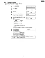
Страница 7: ...4 2 Time Adjustment You can select AM PM or 24 hour clock by programming Make sure that a call is not put on hold 7 KX T2375MXW ...

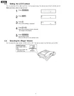
Страница 8: ... level from 1 to 4 by programming Your phone comes from the factory set to 3 Make sure that a call is not put on hold 4 4 Selecting the Ringer Volume You can select the ringer volume to HIGH LOW or OFF Your phone comes from the factory set to HIGH 8 KX T2375MXW ...

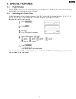
Страница 9: ...h Time The flash time depends on your telephone exchange or host PBX You can select the following flash times 80 90 100 110 200 250 300 400 600 700 ms milliseconds Your phone comes from the factory set to 600 ms Make sure that a call is not put on hold If you are connected via a PBX a longer flash time may be necessary to use PBX functions transferring a call etc Consult your PBX installer for the...

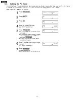
Страница 10: ...l Identification Number prevents unauthorized persons from using your unit The Pin Code is required for the dial lock and call restriction to be set or canceled The factory preset Pin code is 1111 Make sure that a call is not put on hold 10 KX T2375MXW ...

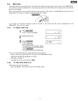
Страница 11: ... locked the number stored in the button can be dialed If you choose not to program emergency numbers but plan to use the dial lock any number programmed into the EMERGENCY button can be accessed 5 4 1 To Set the Dial Lock You can use the following features while the dialing buttons are locked Dialing a number you programmed into the memory of the EMERGENCY button Adjusting the handset and speakerp...

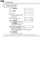
Страница 12: ...eading digits cannot be dialed out 5 5 1 To Set the Call Restriction Make sure that a call is not put on hold If your unit is connected to a PBX this function may not operate Contact your PBX supplier for more information When dialing a phone number with the restricted leading digit s the dialed number will flash on the display but not dialed out 12 KX T2375MXW ...

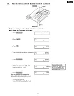
Страница 13: ...5 6 How to Release the Establishment of Dial Lock After this procedure you will be able to establish a new password How to release the establishment of dial lock 13 KX T2375MXW ...

Страница 14: ...6 DISASSEMBLY INSTRUCTIONS Ref No Procedure Shown in Fig To remove Remove 1 1 1 Lower Cabinet Screws 2 6 12 A 5 2 1 2 2 Printed Circuit Board Remove the P C Board 14 KX T2375MXW ...

Страница 15: ...Specific gravity 0 863 Original flux will be replaced daily 7 2 Procedure 1 Temporary fix FLAT PACKAGE IC by soldering on two marked 2 pins Most important matter is accurate setting of IC to the corresponding soldering foil 2 Apply flux for all pins of FLAT PACKAGE IC 3 Solder employing specified solder to direction of arrow as sliding the soldering iron 7 3 Modification Procedure of Bridge 1 Re s...

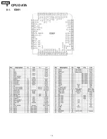
Страница 16: ...8 CPU DATA 8 1 IC801 16 KX T2375MXW ...

Страница 17: ... V Input dc supply voltage V can be powered from Tip and Ring if an ac decoupling inductor is used to prevent loading ac line signals The required V voltage is 6 0 to 11 V 7 5 V nominal at 7 0 mA 17 AGC A capacitor from this pin to VB stabilizes the speaker amp gain control loop and additionally controls the attack and decay time of this circuit The gain control loop limits the speaker amp input t...

Страница 18: ...9 TERMINAL GUIDE OF IC S TRANSISTORS AND DIODES 18 KX T2375MXW ...

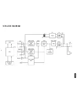
Страница 19: ...10 BLOCK DIAGRAM KX T2375MXW 19 ...

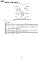
Страница 20: ...11 BLOCK DIAGRAM IC 1 11 1 Communication ICs 20 KX T2375MXW ...

Страница 21: ...ULE BLOCK DIAGRAM 12 2 CONNECTOR PIN ASSIGNMENT Pin no signal Function Enable 1 VDD Power Supply 5V 2 VLCD LCD Power Input 3 VSS Power Gnd 0V 4 DATA Serial Data Input H L 5 WR Write Data H L L 6 CS Chip Selection H L H 21 KX T2375MXW ...

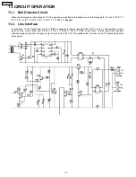
Страница 22: ... Speaker 13 2 Line Interface In talk status L1 RLY output from pin 25 of IC801 changes to low level causing Q103 Q101 to turn on and resulting in a line loop The loop current flows from D101 Q101 Q108 R124 D106 in that order A pulse signal that repeated switches between high and low logic is output from pin 26 of the CPU This switches the line loop on and off generating the dial pulse signal 22 KX...

Страница 23: ...al The Attenuator Control provides a control signal to the TX and the RX attenuator to switch the appropriate signals on and off The Attenuator Control also detects the level of the volume control to automatically adjust for changing ambient conditions 1 Transmission signal path The input signal from the microphone is sent through the circuit via the following path MIC Pin 9 of IC601 Pin 10 of IC6...

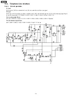
Страница 24: ...urns on thus providing an off hook condition active DC current flow through the circuit and the following signal flow id for the DC loop current T POS101 D101 Q101 Q108 R124 D106 D101 R The receiving signal flows TEL line POS101 Q101 C113 R125 C108 Q109 Q405 Q406 Speaker The transmission signal flows Mic Q421 Q424 C435 R437 Q108 Pos101 Tel Line 24 KX T2375MXW ...

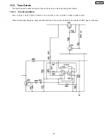
Страница 25: ...sy tone or dial tone during Auto Redial 13 5 1 Circuit operation D101 Q101 C201 R201 R205 Pin 5 of IC201 Pin 1 of IC201 D202 R208 Q201 When the subscriber hangs up check the intermittent tone If cycle tone is detected the collector of Q201 goes to a low logic 25 KX T2375MXW ...

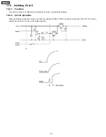
Страница 26: ...alize the microcomputer when it incorporates batteries 13 6 2 Circuit operation When the batteries is inserted into the unit then the voltage is shifted by D304 and power is supplied to the CPU The set can operate beyond point A in the circuit voltage diagram 26 KX T2375MXW ...

Страница 27: ... Q101 Q103 Q104 Can t auto redial Check IC201 Q201 No rings Check D1 IC1 and Q1 can t speak with the speakerphone Check IC601 Can t hold Check Q107 Can t speak with the handset Check handset jack Can t speak with the headset Check headset jack Can t change the volume for speakerphone Check IC801 IC601 Can t change the volume for handset Check IC801 Q405 No volume handset or speakerphone Check IC80...

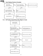
Страница 28: ...14 3 Tone Dialing Problems Hnadset 14 4 No Ringing Sound When Ring Signal is Input 28 KX T2375MXW ...

Страница 29: ...15 CABINET AND ELECTRICAL PARTS LOCATION 29 KX T2375MXW ...

Страница 30: ...16 ACCESSORY AND PACKING MATERIALS 30 KX T2375MXW ...

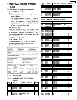
Страница 31: ...15 PQJC314Z BATTERY TERMINAL 16 PQQT22058Z INDICATION LABEL 17 PQSX10186Y KEYBOARD SWITCH 18 PQSX10187Z KEYBOARD SWITCH 19 PQGP10190Z1 PANEL S 17 1 2 MAIN P C BOARD PARTS Ref No Part No Part Name Description Remarks PCB1 PQWPT2375MXW MAIN P C BOARD ASS Y RTL ICS IC1 PQVIBA8206F IC S IC201 PQVINJM2904F IC S IC302 PQVIPS3238NT IC S IC303 PQVIPS3327UT IC IC304 PQVIXCF3702P IC IC601 PQVISC77655S IC S ...

Страница 32: ...R405 ERJ3GEYJ333 33k R406 ERJ3GEYJ335 3 3M R407 ERJ3GEYJ222 2 2k R408 ERJ3GEYJ681 680 Ref No Part No Part Name Description Remarks R409 ERJ3GEYJ223 22k R410 ERJ3GEYJ474 470k R411 ERJ3GEYJ681 680 R412 ERJ3GEYJ682 6 8k R421 ERJ3GEYJ182 1 8k R422 ERJ3GEYJ153 15k R423 ERJ3GEY0R00 0 R424 ERJ3GEYJ334 330k R425 ERJ3GEYJ225 2 2M R426 ERJ3GEYJ272 2 7k R427 ERJ3GEYJ121 120 R428 ERJ3GEYJ562 5 6k R429 ERJ3GEY...

Страница 33: ...2B 0 001 C603 ECUV1H333KBV 0 033 S C605 ECUV1E223KBV 0 022 C606 ECUV1C683KBV 0 068 C607 ECUV1C273KBV 0 027 C608 ECUV1C153KBV 0 015 C609 ECUV1C104KBV 0 1 C610 ECEA1HKA010 1 C611 ECEA1HKA010 1 C612 ECEA1VKS4R7 4 7 S C613 ECUV1C683KBV 0 068 C614 ECEA1EU470 47 S C615 ECEA0JU220 22 C616 ECUV1C104KBV 0 1 C617 ECEA1CKS470 47 S C618 ECEA1VU330 33 S C619 ECEA1VKS4R7 4 7 S C620 ECUV1E183KBV 0 018 S C621 ECE...

Страница 34: ...A to telephone line from the loop simulator 2 This schematic diagram may be modified at any time with the development of new technology Important Safety Notice Components identified by mark have special characteristics important for safety When replacing any of these components use only the manufacturer s specified parts 34 KX T2375MXW ...

Страница 35: ...18 1 MEMO 35 KX T2375MXW ...

Страница 36: ...19 SCHEMATIC DIAGRAM DTMF Hold Music Beep 5 8V 3 7V 3 7V 1 4 5 6 7 9 11 13 14 17 21 24 25 26 28 29 10 18 19 20 27 30 31 32 33 IC651 IC601 IC801 IC903 36 KX T2375MXW ...

Страница 37: ...Set Headset Set Outgoing Signal The voltage during ON Hook is indicated shows the voltage during OFF Hook KX T2375MXW SCHEMATIC DIAGRAM Battery Low 3 8V 3 9V 5 7V 4 2V 5 8V 4 5V 6 3V 3 7V 3 7V 6 3V 1 4 5 6 7 9 11 13 14 17 21 24 25 26 28 29 10 18 19 20 27 30 31 32 33 IC201 IC1 IC304 IC302 IC303 37 KX T2375MXW ...

Страница 38: ...38 KX T2375MXW ...

Страница 39: ...41 KX T2375MXW K KXT2375MXW Printed in Japan ...

Отзывы: