


8
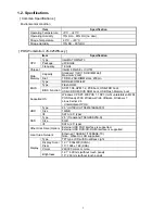
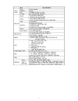
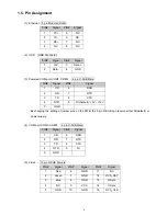
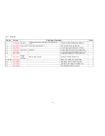
1.5. Pin Assignment
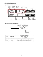
(1) Ethernet
:
8 pin Modular (RJ45)
PIN#
Signal
PIN#
Signal
1 TX+ 5 NC
2 TX- 6 RX-
3 RX+ 7 NC
4 NC 8 NC
(2) USB
:
USB Connector
PIN#
Signal
PIN#
Signal
1 +5V 3 Data
+
2 Data
- 4 GND
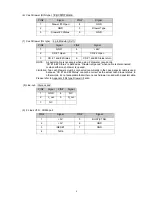
(3) Powered COM port COM1, COM2
:
9 pin D-SUB Male
PIN#
Signal
PIN#
Signal
1 CD 6
DSR
2 RD 7
RTS
3 TD 8
CTS
4
DTR
9
RI (default) / +5V / +12V
5 GND
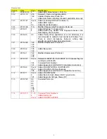
・
By changing the setting of jumper pins on the PWB, the 9 pin D-SUB can receive either RI(default) or
power supply.
(4) COM port COM3, COM4
:
9 pin D-SUB Male
PIN#
Signal
PIN#
Signal
1 CD 6 DSR
2 RD 7 RTS
3 TD 8 CTS
4 DTR 9 RI
5 GND
(5) Video
:
15 pin D-SUB Female
PIN#
Signal
PIN#
Signal
PIN#
Signal
1 Red 6 GND 11 NC
2 Green 7 GND 12
DCA_DAT
3 Blue 8 GND 13
H-Sync
4 NC 9 VCC 14
V-Sync
5 GND 10 GND 15
DCA_CLK
Содержание JS-925WS-010
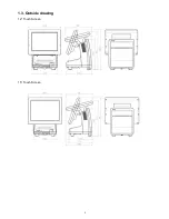
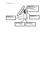
Страница 11: ...5 1 3 Outside drawing 12 Touch Screen 15 Touch Screen ...
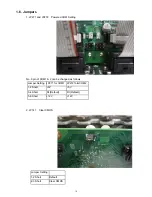
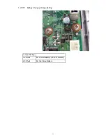
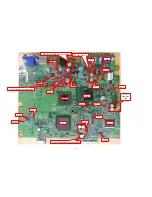
Страница 22: ...14 U214 U291 U292 U322 1 5V generation area 0 9V for Memory Terminator generation area ...
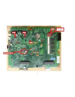
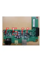
Страница 25: ...17 U1 U2 U7 Audio AMP area ...
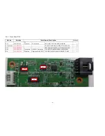
Страница 27: ...19 U7 Q8 Y3 ...
Страница 53: ...45 Please press 2 points ...
Страница 66: ...58 3 5 13 BackLight Test Only OK NG ...
Страница 67: ...59 4 PCB 4 1 Main PCB 4 1 1 Schematic Diagram p49_MAIN_schemati c pdf 40 pages ...
Страница 69: ......
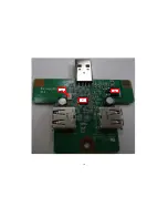
Страница 74: ...96 4 2 Switch LED PCB 4 2 1 Schematic Diagram 93_SW LED_schematic pdf 3 pages ...
Страница 75: ...97 4 2 2 Parts Location p95_SW LED_PCB pdf 1 page Total 4 pages ...
Страница 77: ...99 4 3 Touch Panel PCB 4 3 1 Schematic Diagram p99_TOUCH PANEL_scematic pdf ...
Страница 78: ...100 4 3 2 Parts Location p100_TOUCH PANEL PCB pdf ...
Страница 80: ...102 4 4 JS 925CB 010 Optional I O PCB 4 4 1 Schematic Diagram p102_IO_schematic pdf 6 pages ...
Страница 81: ...103 4 4 2 Parts Location p103_IO_PCB pdf 1page Total 7 pages ...
Страница 82: ......
Страница 84: ...110 4 5 JS 925HU 010 USB HUB PCB 4 5 1 Schematic Diagram p110_USB_schemati c pdf 4 pages ...
Страница 85: ...111 4 5 2 Parts Location p111_USB_PCB pdf ...
Страница 86: ......
Страница 91: ...119 1 3 Disconnect Cables 1 4 Remove 4 screws 1 5 Lift up LCD Unit 1 6 Remove 2 screws ...
Страница 92: ...120 1 7 Remove LCD unit Connect Earth Cable such as the following picture in case of assembly ...
Страница 93: ...121 2 Removal Rear Cover 2 1 Loosen screw 2 2 Lift up Rear Cover Lift up here 2 3 Open Rear Cover ...
Страница 94: ...122 2 4 ...
Страница 96: ...124 3 4 Disconnect the cable 3 5 Remove the 2 screws 3 6 Remove Front PCB ...
Страница 97: ...125 3 7 Disconnect the cable 7 8 28 ...
Страница 98: ...126 3 8 Remove the 2 screws 3 9 Remove Power Supply Shield 9 ...
Страница 99: ...127 Check some points as shown in the following pictures in case of assembly ...
Страница 100: ...128 ...
Страница 101: ...129 3 10 Disconnect the cable 10 ...
Страница 103: ...131 11 ...
Страница 106: ...134 4 4 Remove the 2 screws 4 5 Remove PCB Shield such as shown in the following picture ...
Страница 107: ...135 4 5 Disconnect the cable 4 6 Disconnect the cable 30 ...
Страница 108: ...136 4 7 Remove the 4 screws 4 8 Remove HDD 13 14 15 ...
Страница 109: ...137 4 9 Remove the 3 screws 4 10 Disconnect the cable 4 11 Remove Communication Board ...
Страница 110: ...138 JS 925CB 010 4 12 Remove the 11 screws 4 13 Disconnect the cables ...
Страница 111: ...139 4 14 Remove Main PCB 4 15 Remove DIMM 16 ...
Страница 112: ...140 Side A Side B 17 ...
Страница 113: ...141 Mount the Main PCB with fitting the holes and bosses such as shown in the following pictures in case of assembly ...
Страница 114: ...142 5 Removal Base Frame 5 1 Remove the 2 screws ...
Страница 115: ...143 5 2 Remove the 2 screws 5 3 Remove the base frame ...
Страница 116: ...144 5 4 Remove the 2 screws 5 5 Remove I O Panel 29 ...
Страница 117: ...145 5 6 Remove the 4 hex screws 5 7 Remove the 2 connector cables 18 19 ...
Страница 118: ...146 20 ...
Страница 119: ...147 5 8 Remove the 3 screws 5 9 Remove the 2 pillars 23 22 21 ...
Страница 120: ...148 5 10 Remove 5 screws 24 25 26 27 ...
Страница 124: ...152 3 Remove the 2 screws 4 Disconnect USB Hub Board JS 925HU 010 JS 925HU 010 ...
Страница 125: ...153 5 Remove the 2 screws 6 Remove the 4 screws 7 Remove Hinge ...
Страница 126: ...154 103 8 Loosen the 4 screws until sounds clicky 9 Remove the 4 screws 104 ...
Страница 127: ...155 10 Open Display Front Cover 105 11 Remove the 4 screws ...
Страница 128: ...156 12 Lift up TP LCD Then disconnect Backlight Cables 13 Disconnect LCD cable ...
Страница 129: ...157 14 Disconnect Touch Panel Cable 15 Open TP LCD ...
Страница 130: ...158 16 Remove the 4 screws 17 Remove the tape 116 117 ...
Страница 131: ...159 18 Separate Touch Panel and LCD 106 107 ...
Страница 132: ...160 19 Remove the 3 screws And remove Inverter Board 108 ...
Страница 133: ...161 20 Remove the 2 screws And remove Touch Panel Control Board 109 21 Remove the Cables ...
Страница 134: ...162 110 113 111 114 ...
Страница 136: ...164 6 3 JS 925WS 010 LCD Unit 6 3 1 Disassembly Drawing 1 Remove the 2 screws 2 Remove LCD Cable Cover A and B 201 202 ...
Страница 137: ...165 3 Remove the 2 screws 4 Disconnect USB Hub Board JS 925HU 010 JS 925HU 010 ...
Страница 138: ...166 5 Remove the 2 screws 6 Remove the 4 screws 7 Remove Hinge ...
Страница 139: ...167 203 ...
Страница 140: ...168 8 Loosen the 2 screws until sounds clicky 9 Remove the 4 screws 10 Open Display Front Cover 204 205 ...
Страница 141: ...169 11 Remove the 4 screws 12 Lift up TP LCD Then disconnect Backlight Cables 13 Disconnect LCD cable ...
Страница 142: ...170 14 Disconnect Touch Panel Cable 15 Open TP LCD ...
Страница 143: ...171 16 Remove the 4 screws 17 Remove the tape ...
Страница 144: ...172 18 Separate Touch Panel and LCD 206 207 ...
Страница 145: ...173 19 Remove the 3 screws And remove Inverter Board 208 ...
Страница 146: ...174 20 Remove the 2 screws And remove Touch Panel Control Board 209 21 Remove the Cables ...
Страница 147: ...175 210 213 211 214 ...
Страница 168: ...196 may occur Adjust Display tilt angle with two hands placed on outside bezel edges of Display unit ...
Страница 188: ...216 ...