background image

Chapter


Prepar

ation

Checking CAC data number and CAC data 
during operation

1

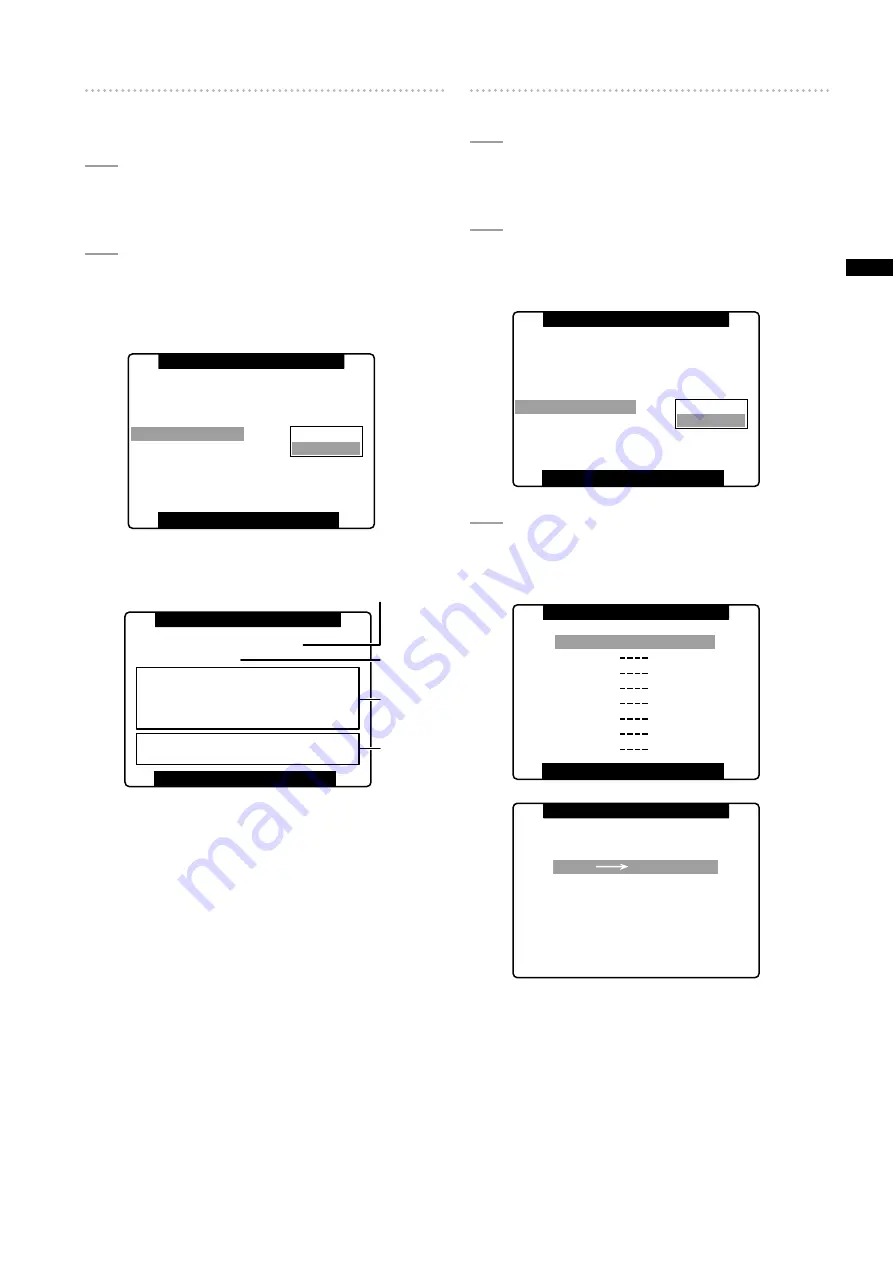
OpentheLENSSETUPscreen.

For details on menu operation, refer to [Using the 
menus] (page 120).

2

TurntheJOGdialbuttontoselectCAC
PROPERTYandselectDISPLAYtoopenthe
CACPROPERTYscreen.

• The CAC property list appears. 

PUSH  MENU  TO  RETURN 

SHADING(USER)

CAC

CAC PROPERTY

CAC CARD READ

CAC FILE DELETE

CAC FILE INIT

DEFAULT

>>>

ON

RETURN

DISPLAY

IRIS ADJUST

>>>

>>>

>>>

SHADING SELECT

LENS SETUP

CAC Property

PUSH  MENU  TO  RETURN  

FILE NO  :  1 

ACTIVE CAC FILE NO : 1 

CAC PROPERTY 

MAKER 

:  FUJINON

TYPE 

:   

XT17X4.5BRM-K14

VERSION  :  1.00-00-0.00 

DATA ERROR 

PLEASE READ CAC CARD 

a

b

c

d

a  Current CAC data number

b  Data number of CAC you wish to check

Turn the JOG dial to select. 

c  CAC data of the specified file (b)

d  Error messages

The file cannot be used if an error message appears. 
Initialize the CAC data or reload the CAC file from an 
SD card. 
For details, see [Initializing CAC File] (page 94) or 
[Loading CAC File From an SD Card] (this page). 

Loading CAC File From an SD Card

1

OpentheLENSSETUPscreen.

For details on menu operation, refer to [Using the 
menus] (page 120).

2

UsetheJOGdialbuttontoselectCACCARD
READ.ThenselectEXECUTEtoopentheCAC
CARDREADscreen.

PUSH  MENU  TO  RETURN 

SHADING(USER)

CAC

CAC PROPERTY

CAC CARD READ

CAC FILE DELETE

CAC FILE INIT

DEFAULT

>>>

ON

>>>

RETURN

IRIS ADJUST

>>>

EXECUTE

>>>

SHADING SELECT

LENS SETUP

3

UsetheJOGdialbuttontoselecttheCACfile
toload.ThenselectYESandpresstheJOG
dialbutton.

PUSH  MENU  TO  RETURN  

ZT17X4.5BRM-K1

CAC CARD READ 

NO 

YES 

CAC FILE NO:1     READ? 

CAC FILE READ 

PUSH SET

Содержание HPX300 - Camcorder - 1080p

Страница 1: ... Instructions Memory Card Camera Recorder Model No AG HPX300P Before operating this product please read the instructions carefully and save this manual for future use This product is eligible for the P2HD 5 Year Warranty Repair Program For details see page 163 ...

Страница 2: ...ch of babies and small children CAUTION TO REDUCE THE RISK OF FIRE OR SHOCK HAZARD AND ANNOYING INTERFERENCE USE THE RECOMMENDED ACCESSORIES ONLY CAUTION Do not jar swing or shake the unit by its handle while the conversion lens or another accessory is attached Due to the added weight of the conversion lens any strong jolt to the handle may damage the unit or result in personal injury CAUTION In o...

Страница 3: ...r television reception which can be determined by turning the equipment off and on the user is encouraged to try to correct the interference by one of the following measures Reorient or relocate the receiving antenna Increase the separation between the equipment and receiver Connect the equipment into an outlet on a circuit different from that to which the receiver is connected Consult the dealer ...

Страница 4: ... are given in the original English language text To obtain the source codes go to the following home page https eww pavc panasonic co jp pro av The manufacturer asks users to refrain from directing inquiries concerning the source codes they have obtained and other details to its representatives 2 Included with this product is software which is licensed under MIT License Details on MIT License can ...

Страница 5: ...33 Standard and Native Recording 34 Standard recording pull down recording 34 Native recording 34 Variable Frame Rate VFR Recording 35 Native VFR Recording 35 Standard VFR recording pulldown recording 35 Using VFR Recording Function 36 Special Recording Modes 38 Pre recording PRE REC 38 Interval recording INTERVAL REC 39 One shot recording ONE SHOT REC 39 Loop recording LOOP REC 40 PROXY Recording...

Страница 6: ... Viewfinder 78 Adjusting Right and Left Viewfinder Position 78 Diopter Adjustment 78 Using the Viewfinder 78 Emphasizing Image Outlines 79 Setting the viewfinder to monochrome mode 79 Handling setup data 80 Configuration of setup data files 80 Handling SD memory cards 81 Formatting Writing and Reading an SD memory card 81 How to Use Scene File Data 82 Saving scene files and other settings on SD me...

Страница 7: ...creen 136 OTHER FUNCTIONS screen 137 DIAGNOSTIC screen 138 OPTION MENU screen 138 Chapter 8 Connecting to External Devices Functionality Provided by Connections to USB 2 0 Connector 139 Connecting to a computer in USB device mode 139 USB host mode 140 Connections to the DVCPRO DV Connector 145 Recording signals input to the DVCPRO DV connector 145 Control of external devices through 1394 connectio...

Страница 8: ...rovides speed effects without using a frame rate converter Native mode also extends the recording time of a P2 card 720P over 60P mode Use of a DVCPRO HD recorder such as the AJ HD1400 or the FOCUS FS 100 hard disk recorder enables the AG HPX300P to make backup recordings with a DVCPRO HD stream from the DVCPRO DV connector 2 1080 480 24P advanced mode Recording 1080 24P or 480 24P makes it possib...

Страница 9: ...temperature Allows fine adjustment after setting the white balance REC REVIEW Provides a quick check of the last few seconds of the most recently recorded clip 4 position optical ND filter provided Chromatic aberration compensation CAC This function automatically corrects the registration error caused by the slight chromatic aberration that the lens cannot compensate for in order to minimize color...

Страница 10: ...ards and can be directly plugged into the PC card slot on a computer 1 The two P2 card slots allow continuous recording on two P2 cards and also offer the following recording capabilities in a memory card camera recorder Card selection In standby status you can instantly select switch to the slot of the card you wish to record on 2 Recorded content can be quickly passed on to editing or transferre...

Страница 11: ...ips A text memo function is also provided Pressing the USER button to which the text memo function has been assigned anywhere in a clip during recording or in preview mode allows you to attach empty post it like text memos up to 100 that can later be filled with text on a PC P2 Viewer Using the camera copy function you can create a new clip by stripping out the desired frames from a clip by copyin...

Страница 12: ...rd recorder External hard disk Computer P2 card USB2 0 DEVICE USB2 0 HOST DVCPRO DV Windows Macintosh Using USB HOST mode to connect an external device via the USB 2 0 connector Page 140 Connecting an external device via the DVCPRO DV connector Page 145 Video equipment Monitor BNC cable composite SDI The contents can be transferred as a data stream digital dubbing The data file is transferred for ...

Страница 13: ...hone receiver PROPAC14 TRIMPAC14 HYTRON50 140 DIONIC90 160 V mount type battery plate Holder plate 6 NP battery holder LCD monitor ENDURA E 7 7S ENDURA E 10 10S 1 The camera is equipped with a battery holder as standard 2 The camera comes with a Fujinon lens 3 For the latest information on P2 cards and SD memory cards not available in the operating Instructions visit the P2 Support Desk at the fol...

Страница 14: ...hing the Shoulder Strap page 97 FRONT AUDIO LEVEL knob screw included For details refer to Attaching the FRONT AUDIO LEVEL Control Knob page 98 Mount cap 4 XLR connector cap 4 BNC cap 4 CD ROM 1 Manufactured by Fujinon Co Ltd 2 This component is part of the lens 3 This component is part of the lens hood 4 This component is part of the camera NOTE Be sure to appropriately dispose of the packing mat...

Страница 15: ...e 97 7 Lens mount 1 3 bayonet mount The lens is attached here For details refer to Mounting the Lens page 89 8 Lens lever Tighten this lever to lock the lens to the lens mount For details refer to Mounting the Lens page 89 9 Mount cap To remove the cap raise the lens lever Replace the cap when a lens is not mounted 10 Lens cable microphone cable clamp This clamp secures the lens and microphone cab...

Страница 16: ...ver REAR Records signals from audio devices or microphones connected to the AUDIO IN CH1 CH2 connectors NOTE To record 2 channel wireless input switch both CH1 and CH2 to W L position and set the menu option WIRELESS TYPE in the AUDIO SETUP screen to DUAL 5 AUDIO IN CH1 CH2 audio channel 1 2 connectors XLR 3 pin Audio devices or microphones may be connected here For details refer to When Using Aud...

Страница 17: ...el 2 Audio Channel 4 1 MIX in the menu option MONITOR SELECT in the AUDIO SETUP screen allows you to change stereo signals to a mixed signal 3 MONITOR volume control Use to control the alarm sound volume and volume of sound output from the monitor speaker and earphones 4 Speaker The speaker outputs EE sound during recording and reproduced sound during playback The speaker emits an alarm sound when...

Страница 18: ...on SEL Changes the speed of the electronic shutter This dial switch returns to its original position when released Each push in the SEL direction changes the shutter speed For details refer to Setting the Electronic Shutter page 51 4 AUTO W B white black BAL switch AWB Automatically adjusts the white balance Set the WHITE BAL switch on the side to A or B and use this switch to adjust the white bal...

Страница 19: ...ng menu or push the AUTO W B BAL switch towards AWB to display the color temperature While the color temperature is still indicated push the AUTO W B BAL switch once again towards AWB to switch between 3200 K and 5600 K A B Pushing the AUTO W B BAL towards AWB will automatically adjust the white balance and save the adjusted value in memory A or memory B For details refer to Adjusting the White Ba...

Страница 20: ...mal speed If this button is pressed when playback is paused the beginning of the clip being played is located in pause mode cue up mode 15 yFF fast forward button In stop mode press this button for fast playback During playback press this button for fast playback at about 4x normal speed If this button is pressed when playback is paused the beginning of the next clip is located in pause mode cue u...

Страница 21: ...lowing SD and SDHC memory card capacities SD memory cards 8MB 16MB 32MB 64MB 128MB 256MB 512MB 1GB 2GB SDHC memory cards 4GB 6GB 8GB 12GB 16GB 32GB For proxy optional recording use 256 MB 512 MB 1 GB 2 GB SD memory cards labeled High Speed or SDHC memory cards For the latest information not available in the Operating Instructions visit the P2 Support Sites at the following Web site https eww pavc ...

Страница 22: ...display mode use this button to access thumbnail menu functions to delete clips for example NOTE Use the cursor SET and EXIT CANCEL buttons to select thumbnails and access menu functions For details see Manipulating Clips with Thumbnails page 101 5 CURSOR and SET buttons Use these buttons to manipulate setting menus the menu bar and thumbnails The four triangular buttons are cursor buttons and the...

Страница 23: ...ton with the TCG switch positioned at SET when the TC PRESET screen and UB PRESET screen are open resets all set values to 0 Use the Cursor SET button to PRESET 6 COUNTER counter display selector button Each press of the button displays the counter value time code user bit and frame rate data in the viewfinder and LCD display 7 TCG time code selector switch Use this switch to set the running mode ...

Страница 24: ...ally lamps OFF Disables the back and rear tally lamps 4 WARNING lamp This lamp starts blinking or lights when an error is detected in the memory card recorder unit LCD Monitor 2 1 1 LCD Monitor The LCD monitor displays the video in the viewfinder Alternatively it can show clips on the P2 card in a thumbnail format For details on the LCD monitor refer to Viewfinder and LCD Menus page 120 In thumbna...

Страница 25: ...LLY switch Use to control the front tally lamp ON Tally lamp goes on OFF Tally lamp goes out 3 Front tally lamp This lamp goes on during recording when the TALLY switch is set to the ON It blinks to indicate warnings 4 Eyepiece 5 Diopter adjusting ring Adjust this ring to suit your vision so that the image in the viewfinder is as clear as possible 6 Eyepiece lock button For details refer to Detach...

Страница 26: ... FUNCTIONS Time zone Time difference Area Time difference Area 00 00 Greenwich 01 00 Central Europe 00 30 01 30 01 00 Azores Islands 02 00 Eastern Europe 01 30 02 30 02 00 Mid Atlantic 03 00 Moscow 02 30 03 30 Tehran 03 00 Buenos Aires 04 00 Abu Dhabi 03 30 Newfoundland Island 04 30 Kabul 04 00 Halifax 05 00 Islamabad 04 30 05 30 Bombay 05 00 New York 06 00 Dacca 05 30 06 30 Yangon 06 00 Chicago 0...

Страница 27: ...t YEAR then press the JOG dial button PUSH MENU TO RETURN 2009 MONTH APR DAY 1 HOUR 13 MINUTE 7 YEAR CLOCK SETTING 6 Turn the JOG dial button to set YEAR to 2009 then press the JOG dial button A year between 2000 to 2037 can be set 7 Turn the JOG dial button to select MONTH then press the JOG dial button 8 Turn the JOG dial button to set MONTH to APR then press the JOG dial button 9 Set DAY HOUR a...

Страница 28: ... pops up to the right Insert a P2 card into the AG HPX300P The P2 CARD ACCESS LED for the appropriate slot indicates the status of the P2 card For details refer to P2 CARD ACCESS LED and status of P2 cards page 29 P2 CARD ACCESS LED 5 Close the card slot cover NOTE To prevent cards from falling out dust from entering and reduce the risk of exposure to static electricity close the card slot cover b...

Страница 29: ...g time after terminating recording playback and other operating modes Removing a P2 card during thumbnail display terminates the thumbnail display To Prevent Accidental Erasure of P2 Card Content To prevent the content of a P2 card being accidentally erased position the write protect switch on the P2 card at Protect Write protect switch NOTE Write protect switchover can be performed while the card...

Страница 30: ...P AVC I 100 DVCPRO HD Approx 64 min AVC I 50 Approx 128 min SD 480i DVCPRO50 Approx 128 min DVCPRO DV Approx 256 min NOTE The above recording time is for normal recording Recording in native mode will extend recording time depending on system mode For details refer to List of recording formats and functions page 44 Use of 32 GB 16 GB and 8 GB P2 cards will provide 1 2 1 4 and 1 8 respectively of a...

Страница 31: ... data or the P2 card may no longer be possible to use in a P2 device To prevent data loss in transferring P2 card data to a PC or write back PC data on a P2 card use P2 Viewer which can be downloaded from the Web site listed below Supported operating systems Windows 2000 Windows XP Windows Vista https eww pavc panasonic co jp pro av support desk e index htm Follow the steps below to use general so...

Страница 32: ...at the recording order is retained even if the power is turned off When the power is next turned on the last card written before powering down will be the target card Setting the switches before shooting and recording When a battery and P2 cards are installed set the switches as detailed below before starting to use your AG HPX300P e a b c d b f a Iris The iris is automatically adjusted when the l...

Страница 33: ...B BAL switch toward AWB to adjust the white balance again For directions on making adjustments see Adjusting the White Balance page 48 and Adjusting the Black Balance page 49 3 Point the camera at your subject to adjust the focus and zoom 4 To use the electronic shutter set the shutter speed and shutter mode For more information see Setting the Electronic Shutter page 51 5 Press the REC button to ...

Страница 34: ...2 5 times over pull down recording Also in native recording the output of camera video and playback video is a 59 94 frame rate Camera recording 2 3 pull down A Ao A B Ae Bo Be Bo Ce Co De Do De B C D C D Recording 1080 24PN Active frame Camera recording 2 3 pull down A A A B B B C C D A B C D D D B C D Recording 720 24PN NOTE In 24P 24PA 24PN native recording and in 30PN native recording at 720P ...

Страница 35: ...ame later than video recorded on a P2 card but this is not a malfunction 1 In 24PN 30PN recording modes when the frame rate is 24 and 30 frames per second respectively audio can also be recorded The time code can be set to Free Run F RUN Standard VFR recording pulldown recording 1 In the SYSTEM SETUP screen set the menu option SYSTEM MODE to 720 59 94P and the menu option REC FORMAT to AVC I 100 6...

Страница 36: ...Only when the menu option REC FORMAT is set to DVCPRO HD 60i in the SYSTEM SETUP screen Shooting at standard speed for producing commercials and TV programs Production aimed at HDTV and SDTV broadcasts for TV audiences must use the frame rate x1 of 30fps 30 frames s The settings below allow you to obtain the kind of playback used for broadcast programs This permits film like video recording of com...

Страница 37: ... HD 60P you can use a nonlinear editing system to generate quick motion effects from the resulting footage Overcranking effects Overcranking produces slow motion playback which is frequently used in climax scenes or for dramatic effects like car chases and action scenes For example selecting a recording frame rate of 60 fps when shooting a 24P recording format yields a slow motion effect that is 2...

Страница 38: ...TEM SETUP screen is set up as described above For details on menu operation refer to Using the menus page 120 2 Set the menu option PREREC MODE to ON in the RECORDING SETUP screen The following indications appear in the special recording display area in the viewfinder Recording P REC lights Pause P PAUSE lights For details refer to Screen displays page 66 3 Press the REC button This setting will r...

Страница 39: ...not available Sound is not recorded Data recorded until the STOP button is pressed in this mode is recorded as a single file There is no output from the DVCPRO DV connector One shot recording ONE SHOT REC This function records a single shot at each unit of time which has been set 1 Check that the SYSTEM SETUP screen is set up as described on page 38 For details on menu operation refer to Using the...

Страница 40: ...g light orange or blinks Note that removing any of the P2 cards will terminate loop recording Irregularity in the input GENLOCK reference signal during loop recording may terminate recording PROXY Recording Function Optional Installing an optional video encoder card AJ YAX800G in P2 card slot 2 makes it possible to record MPEG4 format video time code data and other real time data to P2 cards or SD...

Страница 41: ...ayback Shot marks cannot be set or deleted for video data created in a single hot swap recording session consisting of multiple clips unless all the P2 cards that contain the video data for the entire session are inserted In clips that consist of multiple clips like the one above shot marks can be added only to the first clip of video data Text Memo Recording Function Use this function to add text...

Страница 42: ...ng in pause mode When playback is paused the REW button locates the beginning of the current clip while staying in pause mode NOTE It may take some time to load clip data if playback is started or a thumbnail screen is opened right after removing or inserting a P2 card or turning the power on The thumbnail screen displays UPDATING at such times If a P2 card is inserted while another P2 card is bei...

Страница 43: ...hen turn it back on again REC SIGNAL Selects to record using this camera or from the DVCPRO DV connector REC FORMAT Selects AVC Intra or DVCPRO HD codec and 60i 60P 30PN or 24PN native recording in HD mode Selects DVCPRO50 DVCPRO or DV codec in SD mode CAMERA MODE Selects 60i 30P 24P or 24PA pulldown recording in 1080i or 480i mode ASPECT CONV Selects the video aspect ratio for recording and outpu...

Страница 44: ...rox 160 min Approx 320 min ON 24 Other than 24 720 24PN Native VFR Audio cannot be recorded DVCPRO HD 60P OFF Disabled 720 60P DVCPRO HD Approx 64 min ON 60 30 720 30P Over60P 2 2 Pull Down 24 720 24P Over60P 2 3 Pull Down Other than above 720 60P VFR DVCPRO HD 30PN OFF Disabled 720 30PN Native Approx 128 min ON 30 Other than 30 720 30PN Native VFR Audio cannot be recorded DVCPRO HD 24PN OFF Disab...

Страница 45: ...abled Enabled INTERVAL REC CAMERA INTERVAL 60i 60P 30P only Disabled Enabled at playback 3 Disabled Disabled ONE SHOT REC ONE SHOT LOOP REC LOOP Enabled 3 Disabled 4 Native VFR NORMAL 24PN 30PN ON Disabled Enabled at playback 3 Enabled Enabled Native recording VFR OFF OFF Standard VFR Other than 24PN and 30PN ON Enabled 3 Standerd recording VFR OFF OFF Enabled Enabled Enabled 3 3 DV DVCPRO only Di...

Страница 46: ...60P DVCPRO HD 720 59 94P 4ch 720 59 94P DVCPRO HD ON 60 30 720 30P Over60P 2 2 Pull Down 720 29 97P Over59 94P 2 2 24 720 24P Over60P 2 3 Pull Down 720 23 98P Over59 94P 2 3 Other than above 720 60P VFR 720 59 94P VFR DVCPRO HD 30PN OFF Disabled 720 30PN Native 720 29 97P Over59 94P 2 2 No output 4 ON 30 Other than 30 720 30PN Native VFR Audio cannot be recorded 720 59 94P VFR Muted DVCPRO HD 24PN...

Страница 47: ... Disabled Disabled Disabled 720 60P 720 59 94P 4ch 480 59 94i DVCPRO50 60i Disabled Disabled Disabled 480 60i DVCPRO50 480 59 94i 4ch DVCPRO 60i DVCPRO 2ch DV 60i DV 2ch or 4ch 3 1 60P and 60i is recorded at 59 94P and 59 94i respectively 2 Varies with the SDI SELECT option The table above shows operating conditions when the SDI SELECT option is set to AUTO AUTO depends on SYSTEM MODE 1080i output...

Страница 48: ... see Shooting and Recording Playback Functions Section page 18 3 Place a white pattern at a point where the light conditions match those for the light source of the subject Then zoom in on the white pattern so that white colour appears in the screen A white object cloth or wall may be used instead of a white pattern The illustration below shows the required size for the white space NOTE Do not poi...

Страница 49: ... assigned to the USER MAIN USER1 USER2 buttons For details refer to Assigning functions to USER buttons page 53 PUSH MENU TO RETURN MID GAIN HIGH GAIN ATW ATW TYPE W BAL PRESET USER MAIN 0dB 6dB 9dB Bch 1 USER1 REC REVIEW 3 2K DRS LOW GAIN SW MODE Cancelling auto tracking white balance Press the USER button to which ATW was assigned a second time or change the WHITE BAL switch position If ATW was ...

Страница 50: ...automatically stored in the memory NOTE Ensure that the lens connector is connected and the lens iris is CLOSE During a black balance adjustment light is automatically cut off ABB NG appears when the lens connector has come loose Black balance adjustment is not available during recording Pressing the REC button during ABB adjustment will not start recording on a P2 card ...

Страница 51: ...ross the field of view may appear distorted This is due to the signal read out format of the image sensor MOS sensor and is not a malfunction The red blue and green dots that may appear on the screen at low shutter speeds do not indicate a malfunction Viewfinder displays relating to the shutter See Vie wfinder Screen Status Displays page 65 Placing the Camera recorder in SYNCHRO SCAN Mode To place...

Страница 52: ...ur in video that includes flash light is due to FBC compensation and not indicative of a malfunction Moving subjects may appear to be stationary for an instant Resolution decreases in video exposed to flash light Horizontal lines appear in video footage exposed to flash light Using FBC FBC goes on when the brightness of the lower half of the image differs markedly from the previous half which coul...

Страница 53: ...raises gain by 24 dB Y GET Assigns a function that displays the brightness level at the center of the image DRS Assigns a function that stretches the dynamic range A function that magnifies the dynamic range by compressing the video level in high brightness areas TEXT MEMO Assigns text memory recording SLOT SEL Assigns P2 card slot selection SHOT MARK Assigns the shot marker function MAG A LVL Ass...

Страница 54: ...witch settings and the input system see AUDIO IN switch page 16 NOTE The audio signals recorded on the four channels are output as is SDI Use the AUDIO SETUP screen in the setting menu to make detailed audio settings PUSH MENU TO RETURN FRONT VR CH2 MIC LOWCUT CH1 MIC LOWCUT CH2 MIC LOWCUT CH3 MIC LOWCUT CH4 LIMITER CH1 OFF OFF OFF OFF OFF LIMITER CH2 OFF OFF OFF FRONT VR CH1 AUDIO SETUP Adjusting...

Страница 55: ...ing an input signal in the menu will enable FRONT AUDIO LEVEL control operations for that input signal When the FRONT AUDIO LEVEL control is set to level 10 it controls AUDIO LEVEL CH1 and CH2 PUSH MENU TO RETURN FRONT VR CH2 MIC LOWCUT CH1 MIC LOWCUT CH2 MIC LOWCUT CH3 MIC LOWCUT CH4 LIMITER CH1 OFF OFF OFF OFF OFF LIMITER CH2 OFF OFF OFF FRONT VR CH1 AUDIO SETUP CH3 and CH4 Recording Levels Cond...

Страница 56: ...NG or other abnormality User bits Two types of user bits are provided internally LTC UB recorded as LTC output via the TC OUT connector as LTC embedded in HD SDI and VITC in DVCPRO recorded in the VIDEO AUX area and output as VITC embedded in HD SDI LTC UB enables the recording of user settings time date time codes and similar values the frame rate data for camera capture and external input values...

Страница 57: ...at start of recording 30 frames s DVCPROHD 24PN AVC I100 24PN AVC I50 24PN 24 frames R RUN F RUN 7 NDF locked Every active frame 24 frames Converts and outputs LTC to 30 frames Ouputs LTC Recording TC 24 frames Playback TC 24 frames tc 30 frames Output adjusted to Over 60P based on LTC UB Output adjusted to Over 60P based on LTC UB Other than 24 frames R RUN locked NDF Every active frame 24 frames...

Страница 58: ...B regardless of recorded values Use this setting when a PC or other editing device is to use the user bit frame rate For details see Frame rate information recorded in user bits page 59 To slave lock to the user bits input to the TC IN connector set to EXT In slave mode the UB indicator is highlighted A slave relationship once started continues even after input from the TC IN or DVCPRO DV connecto...

Страница 59: ...his type of data is recorded in VITC UB at all times Setting the setting menu UB MODE to FRM RATE records the information also to the user bits In playback of clips recorded in native mode the same frame rate information as that obtained in playing back the user bits in the VIDEO AUX area is also output to the user bits in the subcode area Frame rate information Frame rate video pull down and time...

Страница 60: ...0 00 to 23 59 59 29 other than 24PN 00 00 00 00 to 23 59 59 23 24PN 00 h 00 m 00 s 00 h min s frm TC PRESET SEL PUSH PUSH REC RUN PRESET PUSH SET q button Shifts the target highlighted digit to the right w button Shifts the target highlighted digit to the left e button Increases the highlighted number by one r button Decreases the highlighted number by one SET button Use to confirm set time code v...

Страница 61: ...s other than 30P capture in 30PN mode 24PN recording at 60P capture Video output 0 1 2 3 22 23 24 25 58 59 60 61 62 63 67 68 Rec start Rec stop Skips Rec start Output time code 00 00 00 00 00 00 00 01 00 11 00 12 00 29 01 00 01 01 02 20 02 20 Recorded video 0 1 2 3 22 23 24 25 58 59 60 61 62 63 67 68 Recorded time code 00 00 00 01 00 02 00 03 00 22 00 23 01 00 01 01 02 10 02 11 02 12 02 13 02 14 0...

Страница 62: ...iewfinder and on the LCD screen and the current clip is divided The continuity of the time code cannot be guaranteed Recording resumes when the signal returns to normal Recording will not resume if interval one shot or loop recording is in progress Example 2 Connecting two or more AG HPX300Ps with one another with one being used as the reference device Reference device VIDEO OUT TC OUT TC IN GENLO...

Страница 63: ...N socket with the external power supply before removing the battery in order to keep the time code generator energized If the battery is removed first there is no guarantee that the time code will stay externally locked External synchronisation of the camera when the time code is externally locked When the time code is externally locked the reference video signals input through the GENLOCK IN conn...

Страница 64: ...ounter Setting and Display Pressing the COUNTER button to view the counter displays the counter value on the time code indicator in the LCD and in the viewfinder The counter value is indicated in Hour Minute Second format The counter value is not displayed during playback The menu option REC COUNTER in the DISPLAY SETUP screen can be set to display two types of counters TOTAL provides a continuous...

Страница 65: ... 1 2 9 9 9 min B 9 0 P 2 L A C K I P A U S E U S E R 1 1394 PROXY C A C F B C 1 0 8 0 i AVC I100 P 3 2K L T BOX 0 dB ND 1 8 3 ND 1 F E B 2 5 2 0 0 8 2 S PO T F 5 6 3 5 9 Z 5 9 9 9 6 0 2 4 P N DR S 1 2 1 2 5 0 C H C H For more information see the following pages Selecting Viewfinder Display Information To select items in the viewfinder screen open the DISPLAY SETUP screen and turn on or off each it...

Страница 66: ...nnector input The colon between the seconds and the frames changes to a period in drop frame mode UB User bit values UB is indicated when the user bit value cannot be correctly read from DVCPRO DV connector input FR Frame rate information for recording FR60I 60i interlace mode 60 fields s FR60P 60P progressive mode 60 frames s FR30P 30P progressive mode 30 frames s FR24P 24P progressive mode 24 fr...

Страница 67: ...the image is indicated in a range between 0 and 109 9 Calendar Month Year 2000 2037 Seconds Hours Day of the month Minutes mmm dd yyyy hh mm ss JAN January FEB February MAR March APR April MAY May JUN June JUL July AUG August SEP September OCT October NOV November DEC December 10 Recording playback frame rate display In native recording the capture frame rate and recording and playback frame rates...

Страница 68: ...attery level in voltages 13 5 V Indication of current battery voltage 25 Media remaining memory display Set the menu option P2CARD REMAIN in the DISPLAY SETUP screen to ONE CARD to display the remaining time on the P2 card being recorded and show the number of the slot it resides in on the left TOTAL displays the remaining time on both cards In a mode check ONE CARD and TOTAL are alternately displ...

Страница 69: ...his message appears when the menu option 1394 CONTROL in the OTHER FUNCTIONS screen is set to EXT and recording is attempted without connecting an external device to the DVCPRO DV connector FORMAT ERR This indicates a P2 card that does not meet the P2 card standard INCOMPATIBLE CARD This message indicates that the inserted card does not meet required standards and cannot be used It may also appear...

Страница 70: ...hen AWB is performed in the PRST position BACK LIGHT OFF Displayed during iris control when back light status is changed by pressing the user button to which BACK LIGHT is assigned DRS ON OFF Displayed when DRS operation has been changed GAIN dB Displayed when GAIN is switched ND NG Displayed when the ND filter is not positioned correctly SCENE Displays the name of a scene file selected by turning...

Страница 71: ...s not cleared 2 Warnings Is not cleared CARD BATT 1 3 Backup unit displays Is not cleared 4 Recording format and system frequency indication 5 Information display Is not cleared 6 Proxy information display optional Is not cleared 7 Letter box recording display 8 Y GET brightness display Is not cleared 9 Calendar Date Time 10 Recording playback frame rate display 11 Audio level meter display LEVEL ...

Страница 72: ...cludes cards selected for recording ACCESSING Indicates a card that is currently read or being written to INFO READING Card in the recognition phase FULL No more space available on the P2 card PROTECTED The P2 card is write protected NOT SUPPORTED The P2 card cannot be used or recognized FORMAT ERROR The P2 card is not properly formatted NO CARD No card has been inserted PROXY optional Proxy card ...

Страница 73: ...uperimposed on signals output via the VIDEO OUT and SDI OUT connectors Audio level meter magnification Press the user button to which MAG A LVL has been assigned to display a magnification of the audio level meter available also when LEVEL METER in the DISPLAY SETUP menu is set to OFF Press the button again to return to normal audio level meter size Turning on MODE CHECK during audio level meter m...

Страница 74: ... the level of the left leaning zebra pattern 2 ZEBRA2 ON SPOT OFF Selects the ZEBRA2 type Underlined values indicate factory defaults SPOT A video level between ZEBRA1 and ZEBRA2 displays a zebra pattern SPOT OFF ON 109 0 ZEBRA 2 DETECT ZEBRA 2 ZEBRA 1 DETECT Image level To display a zebra pattern on video output via the VIDEO OUT connector make the required settings in the OUTPUT SEL screen OUTPU...

Страница 75: ...UT connectors EXPANDED FOCUS ASSIST button Trebles the size of the center of the image The status indication and the zebra pattern disappears and EXPANDED appears at the top of the screen EXPANDED EXPANDED The EXPANDED display is available only during recording and does not work in external input mode NOTE In VIDEO OUT and SDI OUT the center of the image is not magnified and status indications do ...

Страница 76: ...operation refer to Using the menus page 120 At LCD SETTING of the DISPLAY SETUP screen select CHANGE PUSH MENU TO RETURN SAFETY ZONE FOCUS BAR LCD SETTING SELF SHOOT LCD BACKLIGHT SYNC SCAN DISP ON 90 ON RETURN CHANGE DATE TIME OFF NORMAL sec MARKER DISPLAY SETUP 5 Use the JOG dial button to select an item LCD COLOR LEVEL PUSH MENU TO RETURN LCD SETTING LCD BRIGHTNESS LCD CONTRAST 6 Press the JOG ...

Страница 77: ...ting with the LCD display angled 180 degrees towards the lens you can set the menu option SELF SHOOT to MIRROR to horizontally flip the video image on the LCD display and allow you to view a mirror image while shooting Note that only the video image on the LCD monitor is horizontally flipped not the actual video being recorded This function clears any status display waveform and vectorscope displa...

Страница 78: ...le image in the viewfinder Diopter adjusting ring Using the Viewfinder 1 Turn on the POWER switch 2 Use the subscreen in the menu option EVF SETTING in the DISPLAY SETUP screen to adjust screen brightness and contrast For details on menu operations refer to Using the menus page 120 Select CHANGE in the EVF SETTING PUSH MENU TO RETURN EVF PEAK FREQ EVF SETTING EVF B LIGHT EVF COLOR ZEBRA1 DETECT ZE...

Страница 79: ...erature the screen image may have an irregular pink cast When the camera is off there may be black stripes across the screen They disappear when the camera is turned on Image lag may increase at low temperatures but this is not a malfunction Emphasizing Image Outlines Emphasizing outlines of images in the viewfinder and on the LCD monitor makes it easier to focus This function does not affect vide...

Страница 80: ...F3 F4 F5 F6 SCENE FILE 2 F1 F2 F3 F4 F5 F6 SCENE FILE 3 F1 F2 F3 F4 F5 F6 SCENE FILE 4 USER FILE1 USER FILE2 USER FILE3 USER FILE4 USER FILE initial value USER FILE Factory defaults OTHER FUNCTIONS screen USER FILE INTIAL OTHER FUNCTIONS screen USER FILE LOAD SAVE CARD FUNCTIONS screen SCENE FILE LOAD SAVE 2 1 SCENE FILE dial unit 2 All files F1 to F6 Current USER FILE values USER FILE Current ope...

Страница 81: ... not be used or stored in an environment where they may be Exposed to high temperatures humidities Exposed to water droplets or Electrically charged For storage the SD memory card must be kept inserted into the AG HPX300P with the lid closed Formatting Writing and Reading an SD memory card Open the CARD FUNCTIONS screen from the setting menu to format SD memory cards write setting data to SD memor...

Страница 82: ...nstantly using scene file dial You can also use menu options to change set scene file values A modified scene file can be saved to each scene file dial position SCENE FILE dial Note that changing scene files during recording will not change VFR and frame rate settings To make such changes set the camera to recording standby status Factory setting F1 SCENE File suitable for normal shooting F2 SCENE...

Страница 83: ...racter file name Turning the JOG dial button changes the character display in the following order space alphabet A to Z numerics 0 to 9 symbols _ If the RESET button is pressed when the filename has been set the characters are cleared PUSH MENU TO RETURN S P A R K SW POSITION F3 NAME EDIT After you finish setting the filename press the MENU button This completes the NAME EDIT change A change that ...

Страница 84: ...settings on SD memory cards You can save up to four scene file settings or other settings as files on an SD memory card and you can also load them from the card Current scene file settings are automatically saved in the camera and written to an SD memory card When data has been read from an SD memory card the current settings are rewritten at the same time as the data saved inside the unit The dat...

Страница 85: ...creen Reloading Files From an SD Memory Card Perform steps 1 to 3 move to TITLE RELOAD so that YES is displayed in step 5 and press the JOG dial button The file is reloaded To title a file 1 Perform steps 1 to 5 2 Use the JOG dial button to select characters then press the JOG dial button to move to the next character You can input any of the following characters Space A to Z 0 to 9 _ You can eras...

Страница 86: ...truction manual for information about charging Mounting the Battery and Setting the Battery Type Using an Anton Bauer Battery 1 Mount an Anton Bauer battery Lighting control switch Power supply output connector for lighting Anton Bauer Battery NOTE The Anton Bauer battery holder includes both a power supply output connector for lighting and a lighting control switch which are convenient when attac...

Страница 87: ...bout the V mount adapter plate please contact the store where you purchased the camera recorder With the V mount adapter plate installed percent values cannot be displayed when using batteries that show the remaining battery capacity When using an NP battery 1 Mount a V mount adapter plate on the camera Refer to When using a V mount type battery this page 2 Attach a holder plate on the NP battery ...

Страница 88: ...s connected to the unit that power on when the camera powers on example lens wireless microphone receiver We also recommend using the proper DC cable recommended for your external DC power supply When using an external power supply other than the AC adapter check the DC IN socket pin information to ensure correct polarity If a 12 V power supply is accidentally connected to the GND terminal this co...

Страница 89: ... Mark 3 Lower the lens lever to firmly tighten the lens 4 Secure the cable through the cable clamp and plug it into the LENS connector LENS Connector Cable clamp For details on the current provided by the lens terminal refer to page 165 5 Adjust the lens flange back For details refer to Adjusting the Lens Flange Back page 90 NOTE Please refer to the lens instruction manual for guidance on lens han...

Страница 90: ...open the iris Approximately 3 m 3 Place the flange back adjustment chart about 3 m from the lens and adjust the lighting on the chart to obtain an appropriate video output level If the video level is too high use the filters or the shutter 4 Loosen the F f Flange focus ring clamping screw NOTE F b Flange back may be indicated on some lenses 5 Set the zoom ring to the telephoto position either manu...

Страница 91: ...s other than those above perform the White Shading Adjustment described below PUSH MENU TO RETURN SHADING USER CAC CAC PROPERTY CAC CARD READ CAC FILE DELETE CAC FILE INIT DEFAULT USER1 USER2 USER3 OFF IRIS ADJUST SHADING SELECT LENS SETUP White Shading Adjustment NOTE Coloring may occur in the vertical direction near the open setting of the lens iris even when the white shading has been adjusted ...

Страница 92: ...tment ends after a few seconds the message SHADING OK appears When an error message such as SHADING NG LEVEL OVER or SHADING NG LOW LIGHT appears adjust the iris The adjusted value is automatically stored in memory USER1 USER2 USER3 6 If the lens is provided with an extender turn on the extender function and perform steps 2 to 5 again The white shading adjustment need not be readjusted when the ex...

Страница 93: ...wish to check Turn the JOG dial to select c CAC data of the specified file b d Error messages The file cannot be used if an error message appears Initialize the CAC data or reload the CAC file from an SD card For details see Initializing CAC File page 94 or Loading CAC File From an SD Card this page Loading CAC File From an SD Card 1 Open the LENS SETUP screen For details on menu operation refer t...

Страница 94: ...ial to select the CAC file to be deleted Then select YES and press the JOG dial button is indicated when deletion ends PUSH MENU TO RETURN 1 XT17X4 5BRM K14 CAC FILE DELETE 2 3 4 5 6 7 8 NO YES CAC FILE NO 1 DELETE CAC FILE DELETE PUSH SET Initializing CAC File Returning Data to Their Factory Defaults 1 Open the LENS SETUP screen For details on menu operation refer to Using the menus page 120 2 Us...

Страница 95: ... that can be mounted on the camera 1 Open the microphone holder Microphone holder Viewfinder 2 Mount the microphone and tighten the clamping screw Clamping Screw 3 Connect the microphone cable to the MIC IN jack on the camera MIC IN Jack 4 Set the AUDIO IN switch to FRONT depending on the audio channel to be recorded AUDIO IN Switch Using a wireless receiver 1 Remove the lid install the wireless r...

Страница 96: ...AUDIO SETUP screen to DUAL for a 2 channel wireless receiver When Using Audio Devices 1 Connect the audio device to the AUDIO IN jack with the XLR cable 2 Set the AUDIO IN switch to REAR for the channel to which the XLR cable is connected 3 Set the LINE MIC 48V selector switch on the rear panel to LINE AUDIO IN Switch AUDIO IN Jack LINE MIC 48V Selector Switch ...

Страница 97: ...ing the Camera from the Tripod Adapter While holding the red lever down move the black lever in the direction of the arrow and slide the camera backward to remove it Red Lever Black Lever NOTE If the tripod adapter s pin does not return to its original position after the camera has been removed hold the red lever down and move the black lever in the direction of the arrow again in order to return ...

Страница 98: ...tach the accessory knob so that it can be easily operated Screw Marks Screw Accessory FRONT AUDIO LEVEL Control Knob Accessory Remove the screw in the center of the FRONT AUDIO LEVEL control and attach the accessory knob using the screw included When attaching the knob be sure to align the marks on the control with the marks on the knob Attaching the Eye Cup Attach the eye cup by aligning the proj...

Страница 99: ... crane during recording DC OUT connector 1 2 3 4 Cable connector HR10A 7P 4P 73 Hirose Electric Co For details on connecting the connector refer to page 164 Resist ance REC Start Stop Connection example LED 1 GND 2 TALLY OUT The AG HPX300P has open collector output TALLY ON Low impedance TALLY OFF High impedance 3 REC Start Stop switch This pin is connected in parallel with the REC button and the ...

Страница 100: ...10G are turned ON REMOTE connector AJ RC10G NOTE Be sure to turn the POWER switches on the camera and the AJ RC10G off before connecting or disconnecting the controller cable Use only designated cables or optional cables to connect the AJ RC10G Use of other cables could result in equipment damage The USER buttons and MENU button do not work when the AJ RC10G is connected Refer to the Operating Ins...

Страница 101: ...rt of a clip by using the text memo Use a text memo to change thumbnail images Format P2 cards and SD memory cards Uploading and editing clip metadata from the SD memory card Thumbnail Operations Thumbnail Manipulations Overview Thumbnail screens are configured as follows THUMBNAIL OPERATION PROPERTY ALL CLIP SAME FORMAT CLIPS SELECTED CLIPS MARKED CLIPS TEXT MEMO CLIPS DELETE FORMAT REPAIR CLIP R...

Страница 102: ...o Switching the Thumbnail Display page 105 2 Slot numbers and HDD status This function indicates on which P2 card the selected clip is recorded The number of the slot that contains the appropriate P2 card is indicated in yellow If the clip is recorded on more than one P2 card then the numbers of all slots that contain the appropriate cards are indicated The numbers of the other slots are shown in ...

Страница 103: ... displayed for clips such as those which differ in format from the P2 standard 10 Incomplete Clip Indicator Indicates that although a clip is recorded across multiple P2 cards one of these cards is not inserted into a P2 card slot 11 M Shot Mark Indicator This marker is displayed for a clip with a shot mark attached For details refer to Shot Marker SHOT MARK Recording Function page 41 12 P Indicat...

Страница 104: ...r the clip at the cursor location has been played subsequent clips are played back in order When the last clip has been played the thumbnail screen appears NOTE When playing back clips it is not necessary to select the clips blue frames around the thumbnails Clips with clip numbers displayed in red cannot be played During playback pressing the REW button starts 4X speed reverse playback and the FF...

Страница 105: ... thumbnail display by selecting one of the following items ALL CLIP Display all clips SAME FORMAT CLIPS Displays clips of the current system format SELECTED CLIPS Display randomly selected clips MARKED CLIPS Display clips with shot marks attached TEXT MEMO CLIPS Display clips with text memo data attached SLOT CLIPS Display clips recorded in the P2 card inserted in the specified slot When this item...

Страница 106: ...ail menu to confirm the position of the thumbnail the number of frames from the top of the clip Since thumbnails come generally from the top of the clip 0 is displayed Shot Mark A shot mark can be added to a clip thumbnail to distinguish this clip from other clips 1 Press the THUMBNAIL button The thumbnail screen appears on the LCD monitor 2 Use the cursor buttons to move the pointer over the clip...

Страница 107: ...clip can have up to 100 text and voice memos in combination Note that the unit is not capable of adding or showing voice memos Playing back a clip at the position where a text memo is recorded 1 Press the THUMBNAIL button The thumbnail screen appears on the LCD monitor 2 Press the THUMBNAIL MENU button and select THUMBNAIL TEXT MEMO CLIPS from the thumbnail menu The clip thumbnails with text memos...

Страница 108: ...ng a text memo to break a clip and copy the necessary portion 1 Select the desired text memo in a clip by carrying out steps 1 3 for Playing back a clip at the position where a text memo is recorded page 107 2 Move the pointer to the desired text memo and then press the SET button You can select more than one text memo 3 Press the THUMBNAIL MENU button to select OPERATION COPY 4 Use the cursor but...

Страница 109: ...ect OPERATION REPAIR CLIP from the thumbnail menu When a confirmation screen asks you to confirm that you want to repair the clip use a cursor button and the SET button to select YES if you want to restore the clip Reconnection of Incomplete Clips Incomplete clips may be generated when clips recorded on multiple P2 cards connected clips are separately copied to different cards The reconnection fun...

Страница 110: ... SET button The clip that was being copied is deleted at the destination When identical clips exist on the destination card the OVERWRITE is displayed Select YES or NO 1 Regarding SD memory cards to be used see SD memory card precautions page 21 Setting of Clip Meta Data Information such as the name of the person who shot the video the name of the reporter the shooting location or a text memo can ...

Страница 111: ...del name of the device SHOOT 2 Displays SHOOTER name of the person who shot the video START DATE start date of shooting END DATE end date of shooting and LOCATION ALTITUDE LONGITUDE LATITUDE SOURCE PLACE NAME altitude longitude latitude and source of the information and name of the location SCENARIO Displays PROGRAM NAME SCENE NO and TAKE NO NEWS Displays REPORTER name of the reporter PURPOSE purp...

Страница 112: ...etadata has been turned off Same as GLOBAL CLIP ID UMID data TYPE2 USER CLIP NAME to be recorded If clip metadata has been read in Uploaded data COUNT value 1 If no clip metadata has been read in or if the setting for recording clip metadata has been turned off Same as CLIP NAME 1 The COUNT value is indicated as a four digit number The COUNT value is incremented each time a new clip is captured if...

Страница 113: ...ing a clip on two P2 cards Recording start Recording pause Clip 1 COUNT value 0003 Clip 2 COUNT value 0004 1st card 2nd card If the clip thumbnails are displayed as shown in the example above or their properties are indicated using a P2 device the thumbnail and COUNT value of clip 1 will be displayed Clearing uploaded metadata Select META DATA INITIALIZE from the thumbnail menu and press the SET b...

Страница 114: ...e video encoder card NOTE When PROXY CARD ERROR is indicated in the viewfinder either check the video encoder card or set the unit so that proxy recording is not performed Formatting a P2 Card 1 Press the THUMBNAIL button The thumbnail screen appears on the LCD monitor 2 Press the THUMBNAIL MENU button and select OPERATION FORMAT from the thumbnail menu When the screen shown below appears select t...

Страница 115: ...il display mode can be customized to suit your preferences 1 Press the THUMBNAIL button The thumbnail screen appears on the LCD monitor 2 Press the THUMBNAIL MENU button and select THUMBNAIL SETUP from the thumbnail menu The following screen appears INDICATOR Select which indicators you want to show on thumbnails and which you want to hide ALL HIDE ON No indicators are displayed OFF Indication No ...

Страница 116: ...n to flash momentarily indicating that the there are no more clips which can be played back THUMBNAIL INIT Returns the above thumbnail display settings to their factory default values Move the cursor to this option and press the SET button Select YES in the confirmation screen that appears EXIT Returns to the previous menu Properties Properties display clip properties and P2 card status It is poss...

Страница 117: ...e modified metadata on the clip and return to the metadata window NOTE LOCATION recording location data data for a SHOOT cannot be deleted independently Thus by setting ALTITUDE to empty will also delete the LONGITUDE and LATITUDE settings The metadata for a clip with the incomplete clip indicator cannot be modified Metadata on clips recorded on multiple P2 cards must be modified when all P2 cards...

Страница 118: ... cards will display the symbol RUN DOWN CARD The maximum number of overwrites on the P2 card has been exceeded DIR ENTRY NG CARD The directory structure on the P2 card is not supported For details on P2 card status indications refer to 2 P2 Card Status remaining free space When USED is selected 2 5 1 3 4 1 Write protect Mark The mark appears if the P2 card is write protected 2 P2 Card Status used ...

Страница 119: ...mation on formatting SD memory cards see Formatting SD memory cards page 115 NOTE The indication of remaining capacity on an SD memory card PROXY REM provides only a rough estimate of remaining capacity and may differ from actual remaining capacity SD and SDHC cards with Speed Class Ratings may indicate recording times that are significantly lower than actual capacity especially when used for reco...

Страница 120: ... EXIT 2 SYSTEM SETUP 3 SW MODE 4 RECORDING SETUP 5 AUDIO SETUP 6 OUTPUT SEL 7 DISPLAY SETUP 8 BATTERY SETUP 1 SCENE FINE MAIN MENU 2 Use the JOG dial button or the Up and Down cursor buttons to highlight the function you want to change PUSH MENU TO EXIT 2 SYSTEM SETUP 3 SW MODE 4 RECORDING SETUP 5 AUDIO SETUP 6 OUTPUT SEL 7 DISPLAY SETUP 8 BATTERY SETUP 1 SCENE FINE MAIN MENU 3 Press the JOG dial ...

Страница 121: ...ntain this position Fast DOWN Hold down the JOG dial button while turning it downwards and maintain this position Initializing the menu settings The menu settings contain both the user file settings and the scene file settings You can initialize them separately To initialize scene files i e all the settings other than the scene file settings Select INITIAL in USER FILE of the OTHER FUNCTIONS scree...

Страница 122: ... LEVEL CH3 UB MODE AUTO LEVEL CH4 25M REC CH SEL AUDIO SETUP TEST TONE page 130 F MIC POWER R MIC POWER OUTPUT SEL SDI SELECT MONITOR SELECT page 132 SDI META DATA F MIC LEVEL SDI EDH R MIC CH1 LEVEL DOWNCON MODE R MIC CH2 LEVEL VIDEO OUT CHAR HEADROOM VIDEO OUT ZEBRA WIRELESS WARN TC OUT WIRELESS TYPE TC VIDEO SYNCRO 1394 AUDIO OUT DISPLAY SETUP EVF PEAK LEVEL page 132 EVF PEAK FREQ EXT DC IN SEL...

Страница 123: ...36 CAC FILE DELETE CAC FILE INIT OTHER FUNCTIONS USER FILE IRIS ADJUST page 137 1394 CONTOROL 1394 CMD SEL ACCESS LED ALARM CLOCK SETTING TIME ZONE GL PHASE H PHASE VERSION MENU INIT MODEL NAME SERIAL NO DIAGNOSTIC OPERATION page 138 OPTION MENU 1 1394 STATUS page 138 1394 CONFIG 1 To open the OPTION MENU hold down the DISP MODE CHK button and press the MENU button ...

Страница 124: ...can shutter speeds to enable the operator to synchronize the camera to computer monitors This function only displays the shutter speeds Use the SYNCHRO SCAN switch to set a shutter speed Set values displayed values are assigned to the current scene file and manipulated using the LOAD SAVE and INIT functions For details refer to Placing the Camera recorder in SYNCHRO SCAN Mode page 51 1 60 0 Displa...

Страница 125: ...r video with greater brightness Contrast softens as a result B PRESS Produces sharper contrast than LOW CINE LIKE D Applies a gamma curve to produce video with a cine like feel CINE LIKE V Applies a gamma curve to produce high contrast video with a cine like feel A lens aperture set lower than normal video level approx 1 2 is recommended when using cine like gamma to enjoy the full benefit of the ...

Страница 126: ...tion is always set to CAMERA when the power is turned on Not available when the menu option REC FORMAT is set to AVC Intra or DVCPRO HD during native recording REC FORMAT Selects the recording codec as well as shooting and recording modes when SYSTEM MODE is 1080 59 94i AVC I100 60i AVC I100 30PN AVC I100 24PN Uses the AVC I 100 codec for recording Shooting and recording at 60i 30PN native recordi...

Страница 127: ... lenses and anamorphic lenses ON OFF ASPECT CONV Selects the aspect ratio for recording at 480i SIDE CROP Crops the right and left edges of the image LETTER BOX Adds black bands at the top and bottom of the image SQUEEZE Compresses the image horizontally Not available when SYSTEM MODE is set to 1080 59 94i or 720 59 94P SETUP Selects the setup level for the 480i video signal 0 Setup is switched to...

Страница 128: ... position of the WHITE BAL switch 3 2K 5 6K USER MAIN Sets the function assigned to the USER MAIN button REC REVIEW SPOTLIGHT BACKLIGHT ATW ATWLOCK GAIN 24 dB Y GET DRS TEXT MEMO SLOT SEL SHOT MARK MAG A LVL PRE REC PC MODE WFM FBC For details refer to Assigning functions to USER buttons page 53 When a remote controller AJ RC10G is connected the SPOTLIGHT and BACKLIGHT functions are not available ...

Страница 129: ...rm 2frm 4frm 8frm 16frm 1s For details refer to One shot recording ONE SHOT REC page 39 Available only when REC FUNCTION is set to ONE SHOT INTERVAL TIME Sets the time interval of interval recording 2frm 4frm 8frm 16frm 1s 2s 5s 10s 30s 1min 5min 10min For details refer to Interval recording INTERVAL REC page 39 Available only when REC FUNCTION is set to INTERVAL START DELAY This delays the start ...

Страница 130: ...tes for wireless receiver input REAR Operates for the rear microphone input OFF Turns off the filter for all inputs MIC LOWCUT CH2 1 Sets the CH2 microphone low cut filter Same setting as MIC LOWCUT CH1 OFF factory default setting MIC LOWCUT CH3 1 Sets the CH3 microphone low cut filter Same setting as MIC LOWCUT CH1 OFF factory default setting MIC LOWCUT CH4 1 Sets the CH4 microphone low cut filte...

Страница 131: ...rophone ON OFF R MIC POWER Turns on and off the phantom power supply for the rear microphone ON Turns on the phantom power supply to the microphone when the rear LINE MIC 48V switch is set to 48V OFF Does not supply phantom power to the microphone even when the rear LINE MIC 48V switch is set to 48V MONITOR SELECT Switches the output signal to AUDIO OUT earphones and speaker when the MONITOR SELEC...

Страница 132: ...ing is disabled when RC10 remote controller is connected in which case RC10 settings have priority VIDEO OUT ZEBRA Specifies whether or not zebra pattern is superimposed on VIDEO OUT signals ON Displays a zebra pattern also on images output via the VIDEO OUT connector OFF The zebra pattern is not displayed in video output from the VIDEO OUT connector TC OUT Sets the time code type output from the ...

Страница 133: ...tes accuracy of focusing ON Displays the focus bar OFF Does not display the focus bar This function is not interlocked with the FOCUS ASSIST button LCD SETTING Makes it possible to set video color level brightness and contrast displayed in the LCD monitor in a subscreen Subscreen LCD COLOR LEVEL LCD BRIGHTNESS LCD CONTRAST SELF SHOOT Sets the LCD screen display when taking self portraits NORMAL Th...

Страница 134: ...upply type AC ADAPTER AC adapter BATTERY Battery BATTERY SELECT Sets the battery type PROPAC14 TRIMPAC14 HYTRON50 HYTRON140 DIONIC90 DIONIC160 NP L7 ENDURA7 ENDURA10 ENDURA D PAG L95 BP GL65 95 NiCd14 TYPE A TYPE B BATTERY MODE Sets near end AUTO Automatically selects one of the battery types selected in BATTERY SELECT MANUAL Manually sets the near end voltage PROPAC14 NEAR Sets the near end volta...

Страница 135: ... NiCd14 END Sets the end voltage for NiCd14 Adjustable in 0 1 V units 11 0 V 13 1 V 15 0 V TYPE A FULL Sets the full voltage for TYPE A Adjustable in 0 1 V units 12 0 V 15 7 V 17 0 V TYPE A NEAR Sets the near end voltage for TYPE A Adjustable in 0 1 V units 11 0 V 13 7 V 15 0 V TYPE A END Sets the end voltage for TYPE A Adjustable in 0 1 V units 11 0 V 13 3 V 15 0 V TYPE B FULL Sets the full volta...

Страница 136: ...YSTEM SETUP screen Set the menu option PC MODE to OFF before making file operations LENS SETUP screen Item Setting Notes SHADING SELECT Sets one of the following shading compensation parameters DEFAULT Standard lens setting USER1 User setting 1 USER2 User setting 2 USER3 User setting 3 OFF Sets shading compensation to OFF SHADING USER Selects whether or not to set shading parameters to SHADING SEL...

Страница 137: ...al one shot and loop recording ACCESS LED Determines whether or not the P2 CARD ACCESS LED should light ON OFF ALARM Sets the alarm sound output when an alarm occurs HIGH LOW OFF CLOCK SETTING Sets the internal calendar date For details see Setting Date and Time of Internal Clock page 26 TIME ZONE Sets the time difference relative to Greenwich Mean Time GMT 12 00 0 00 13 00 For details see Setting...

Страница 138: ...dicates serial number of this camera OPERATION Indicates the time of the camera has been on OPTION MENU screen Open this menu by holding down the DISP MODE CHK button and when shooting status appears press the front MENU button Use this function to check connection status during nonlinear editing Item Setting Notes 1394 STATUS Opens the subscreen that shows 1394 status Subscreen FORMAT Format of i...

Страница 139: ...ption USER MAIN USER1 USER2 in the SW MODE screen to assign PC MODE settings to a user button Note that the USER button functions are not available when the menu is open To make a USB connection you must first install the P2 software on the supplied CD ROM on the computer Select the AG HPX300 driver This USB driver supports only the Windows operating system For details refer to the installation ma...

Страница 140: ...s connected to a hard disk drive the HDD icon appears at the top right of the screen If the icon lights red this indicates that data cannot be copied to or from the hard disk Check hard disk drive type For details on hard disk drives refer to Thumbnail Screen page 102 NOTE The USB host mode allows playback of P2 cards but not recording of camera video or external input And clips on the hard disk m...

Страница 141: ...d by the camera This format allows thumbnail display loading and write back of data in card units and write back of data and formatting in clip units P2STORE This is the P2 STORE AJ PCS060G hard disk drive Cannot be used for writing data This format displays thumbnails write back data in card units and write back data in clip units FAT The basic primary partition on a PC is FAT 16 or FAT 32 The ro...

Страница 142: ...partition 10 SERIAL Indicates the serial number of P2 card that originally recorded the data in the partition 11 VERIFY Indicates verify settings and results when data was recorded to a partition ON FINISHED Runned verify and verify results were matched ON FAILED Runned verify but verify results could not be matched OFF Did not run verify No verify information available NOTE Hard disk drives forma...

Страница 143: ...SETUP in the thumbnail menu and set VERIFY to OFF This speeds up the write time but does not verify the written data Selecting ALL SLOT writes the data on all inserted P2 cards inserted in the camera to the hard disk drive NOTE A TYPE S hard disk drive can write data in card units Up to 23 P2 cards can be saved to a hard disk drive The P2 card data recorded on a hard disk drive are recognized as s...

Страница 144: ...t Refer to Reconnection of Incomplete Clips page 109 Hard disk drive precautions Use hard disk drives including P2 STORE AJ PCS060G according to the following conditions Operate hard disk drives within their operating specifications temperature etc Do not use hard disk drives in locations that are unstable or exposed to vibration Some hard disk drives may not operate normally SATA serial ATA or PA...

Страница 145: ...ize to an external reference signal Signals output from the VIDEO OUT or AUDIO OUT connectors differ from actual input signals Use such signals for monitoring The following functions do not operate Pre recording function Loop recording function Interval recording and one shot recording function Time Code and User Bits When input from the IEEE1394 interface is selected the time code or user bits in...

Страница 146: ...nnection reinsert the 1394 cable or turn the camera off and then turn it back on again Make sure that the camera and all connected devices are connected to ground or connected to a common ground If the equipment cannot be connected to ground turn off all connected devices before connecting or disconnecting an IEEE1394 cable When connecting the unit to a device with a 4 pin connector connect the ca...

Страница 147: ...ard is inserted keeps blinking in green or if there is no display recording is not possible on that particular P2 card 1 2 Inspecting the Camera Unit 1 Set the zoom to electric zoom mode and check the zoom operation Check that the image changes to telephoto and wide angle 2 Set the zoom to manual zoom mode and check the zoom operation Turn the manual zoom lever to check that the image changes to t...

Страница 148: ...eck that playback is operating normally 6 Use the USER button to which the SLOT SEL function has been assigned to select P2 cards for recording when more than one P2 card is inserted in the card slots Repeat the operations in Steps 2 to 3 and 5 to check that recording and playback operate properly Inspecting the Audio Level Automatic Adjustment 1 Set the AUDIO SELECT CH1 and CH2 switches to AUTO 2...

Страница 149: ...s page 58 for the setting procedures 2 Set the time code Please refer to Setting the Time Code page 60 for the setting procedures 3 Set the TCG switch to R RUN Press the COUNTER button to display the time code on the LCD monitor or in the viewfinder 4 Press the REC button Check that the counter display number changes as recording progresses 5 Press the REC button again Check that recording stops a...

Страница 150: ...ob clicks into place NOTE When outdoors never carry or set up the camera with the eyepiece facing up to prevent sunlight which could damage the camera from entering Cleaning Inside the Viewfinder Detach the eyepiece to remove dust from the LCD screen inside the viewfinder For details refer to Detaching the eyepiece this page Use a soft brush or blower brush to remove dust from the LCD screen NOTE ...

Страница 151: ...2 card fully recorded P2 FULL Blinks red appears only for 3 seconds in MCR mode Blinks 4 times per second after completion of recording Lights after completing recording Continuous tone after completing recording No more space on P2 cards left for recording Stop recording 3 Delete clips that are no longer needed or insert a new card 5 Recording error REC WARNING Cause indication 2 Blinks red Blink...

Страница 152: ...te or less This warning appears only during recording Replace or insert additional P2 cards 1 P2 SYSTEM ERROR cause indication P2 MICON ERROR The P2 microprocessor does not respond P2 CONTROL ERROR A P2 recording control error has occurred CAM MICON ERROR The camera microprocessor does not respond 2 REC WARNING cause indication CARD ERROR P2CARD error indicates the number of the slot of the card w...

Страница 153: ...et Insert all P2 cards with recorded clips and confirm that the incomplete clip indicators disappear and then add shot marks NO CARD No P2 or SD card is inserted Insert compatible media NO COPY TO SAME CARD A clip cannot be copied to the card storing the original clip Copy the selected clip to a card that does not contain the original clip NO FILE The designated file is not found Check the file NO...

Страница 154: ...nect the USB cable If the hard disk does not operate normally turn it off and turn it back on again MISMATCH COMPONENT Copying cannot be made because the destination card is in the wrong format Use a P2 card with the same model number or import video in clip units P2 CARD IS UNFORMATTED The P2 card is not formatted Use a formatted P2 card PLEASE FORMAT P2 CARD This warning indicates that data coul...

Страница 155: ...t pages Besides access to PASS completing customer registration has a number of other benefits For further details refer to the PASS P2 Asset Support System website https eww pavc panasonic co jp pro av 2 Checking the current version of the firmware using the unit and performing the update Check firmware version of the camera in the DIAGNOSTIC screen Then access the site listed in the NOTE below t...

Страница 156: ...CLOCK SETTING 137 MENU COLOR TEMP Ach 124 MENU COLOR TEMP Bch 124 Connector signal 164 Control of external devices 146 Copying 109 Counter 64 cue up 42 D Date and Time 26 MENU DATE TIME 133 DC power 88 Deleting 108 MENU DETAIL CORING 124 MENU DETAIL LEVEL 124 MENU DIAGNOSTIC screen 138 Dimensions 160 MENU DIONIC160 NEAR 134 MENU DIONIC90 NEAR 134 Diopter Adjustment 78 MENU DISPLAY SETUP screen 132...

Страница 157: ... CH3 130 MENU MIC LOWCUT CH4 130 Microphone 95 MENU MID GAIN 128 MODE CHECK 72 MENU MODEL NAME 138 MENU MONITOR SELECT 131 N MENU NAME EDIT 126 Native recording 34 Native VFR Recording 35 MENU NEAR END CANCEL 135 MENU NiCd14 END 135 MENU NiCd14 NEAR 135 Normal Recording 33 Normal speed playback 42 MENU NP L7 NEAR 134 O MENU ONE SHOT TIME 129 One shot recording ONE SHOT REC 39 MENU OPERATION 138 ME...

Страница 158: ...ions 160 Standard VFR recording 35 MENU START DELAY 129 MENU SW MODE screen 128 MENU SYNC SCAN DISP 133 SYNCHRO SCAN 51 MENU SYNCHRO SCAN 124 MENU SYSTEM MODE 126 MENU SYSTEM SETUP screen 126 T MENU TC MODE 129 MENU TC OUT 132 MENU TC VIDEO SYNCHRO 132 MENU TEST TONE 131 Text Memo 41 THUMBNAIL 101 Thumbnail Switching 105 Selecting 104 Changing 106 menu 101 Time Code 60 Time Data 56 Time zone 26 ME...

Страница 159: ...1 warnings 69 Waveform monitor function 77 MENU WFM 128 White Balance 48 White Shading Compensation 91 wireless receiver 95 MENU WIRELESS TYPE 131 MENU WIRELESS WARN 131 Z Zebra pattern 74 MENU ZEBRA1 DETECT 133 MENU ZEBRA2 133 MENU ZEBRA2 DETECT 133 MENU ZOOM 133 ...

Страница 160: ... information Ambient operating temperature humidity 0 C to 40 C 32 F to 104 F 10 to 85 relative humidity Storage temperature 20 C to 60 C 4 F to 140 F Weight Approx 3 6 kg 7 93 lb camera unit only Approx 5 0 kg 11 02 lb Including lens and lens hood Dimensions Camera only With supplied lens 246 mm width 251 mm height 441 mm depth 9 11 16 inches width 9 7 8 inches height 17 3 8 inches depth excludin...

Страница 161: ...12 15 18 20 21 22 24 25 26 27 28 30 32 34 36 40 44 48 54 60 fps frames per second Horizontal resolution 1000 TV lines or more center Memory card recorder Unit Recording media P2 card Recording Formats AVC Intra 100 AVC Intra 50 DVCPRO HD DVCPRO50 DVCPRO DV formats switchable Recording Playback Time AVC Intra 100 DVCPRO HD 8 GB 1 approx 8 min 16 GB 1 approx 16 min 32 GB 1 approx 32 min 64 GB 1 appr...

Страница 162: ...ra 100 AVC Intra 50 DVCPRO HD 48 kHz 16 bits 4CH DVCPRO50 48 kHz 16 bits 4CH DVCPRO DV 48 kHz 16 bits 2CH 4CH switchable Head room 20 dB 18 dB Menu selectable Video Input Output Unit GEN LOCK IN BNC 1 1 0 V P P 75 Ω VIDEO OUT BNC 1 1 0 V P P 75 Ω SDI OUT BNC 2 0 8 V P P 75 Ω HD compliant with SMPTE 292M 296M 299M SD compliant with SMPTE 259M C 272M A ITU R BT656 4 Audio Input Output Unit MIC IN XL...

Страница 163: ... Panasonic Canada Inc privacy policy does not apply and is not applicable in relation to any information submitted This link is provided to you for convenience Programme de réparations sous garantie pendant 5 ans pour un P2HD 1 Nous vous remercions d avoir choisi cet appareil Panasonic P2HD Inscrivez vous comme utilisateur de cet appareil pour bénéficier d une garantie spéciale donnant droit à des...

Страница 164: ...Electric Co PUSH 1 3 2 AUDIO IN 1 GND 2 AUDIO IN H 3 AUDIO IN C Panasonic Part No K1AY103A0001 Manufacturer Part No HA16PRM 3SG 72 Hirose Electric Co PUSH 1 3 2 REMOTE 1 CAM DATA H 2 CAM DATA C 3 CAM CONT H 4 CAM CONT C 5 R C ON 6 R C VIDEO OUT 7 R C VIDEO GND 8 NC 9 UNREG 12 V Max 0 6 A 10 GND Panasonic Part No K1AY110JA001 Manufacturer Part No HR10A 10R 10SC 71 Hirose Electric Co 1 2 4 5 6 7 8 9...

Страница 165: ... for a wireless receiver 6 RX ON Remote power output to a wireless receiver 7 RF WARN RF warning input from a wireless receiver 8 RM5 Not used 9 RM4 Not used 10 SPARE 1 Not used 11 SPARE 2 Not used 12 EXT CLK Not used 13 CLK SHIELD Not used 14 CH 2 SHIELD GND 15 CH 2 HOT Audio input from a wireless receiver CH2 HOT 16 CH 2 COLD Audio input from a wireless receiver CH2 COLD 17 5 6 V Power supply fo...

Страница 166: ...al in other Countries outside the European Union This symbol is only valid in the European Union If you wish to discard this product please contact your local authorities or dealer and ask for the correct method of disposal ...

Отзывы: