background image

S-15

MK3

MK4

C3302

C3303

C3906

C7001

C

7

0

0

2

C

7

0

0

3

C

7

0

0

4

D7002

D7003

14

13

12

11

10

9

8

7

6

5

4

3

2

1

HS3901

1

5

6

1

0

I

C

7

0

0

1

L

7

0

0

1

L

B

3

3

0

1

L

B

3

3

0

2

L

B

3

3

0

3

L

B

3

3

0

4

L

B

3

3

0

5

L

B

3

3

0

6

2

1

P7001

R

3

3

1

1

R

3

3

1

2

R

3

3

1

3

R

3

3

1

4

R

3

3

1

5

R

3

9

0

7

R7001

R

7

0

0

2

R

7

0

0

3

R

7

0

0

4

R

7

0

0

6

R7007


7

0

9

8

R

7

0

9

9

4

3

2

1

T

7

0

0

1

MK1

MK2

12

10

5

1

JK3301

HDC-HS700

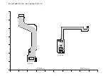
Strobe P.C.B.

(Foil Side)

10

9

8

7

6

5

4

3

2

1

G

F

E

D

C

B

A

(Foil Side)

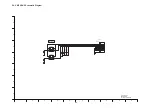
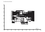
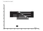
S5.1.2. Strobe P.C.B. (Foil Side)

Содержание HDC-HS700EB

Страница 1: ...bution is a violation of law ORDER NO VM1002001CE B27 High Definition Video Camera Model No HDC HS700P HDC HS700PC HDC HS700PU HDC HS700EB HDC HS700EC HDC HS700EE HDC HS700EF HDC HS700EG HDC HS700EP HDC HS700GC HDC HS700GN HDC HS700GT Vol 1 Colour K Black Type 4 ...

Страница 2: ... than U S A and Canadian Market 8 3 4 How to Define the Model Suffix NTSC or PAL model 9 3 5 Precautions for Handling HDD 10 3 6 Formatting 14 4 Specifications 15 5 Location of Controls and Components 18 6 Service Mode 21 6 1 Drive Information Display 22 6 2 HDD Self Check Execution 22 6 3 Lock Search History Indication 23 6 4 Power ON Self Check Result Display 23 6 5 HDD Hardware Test 24 7 Servic...

Страница 3: ...exposed to shock hazards 1 2 Leakage Current Cold Check 1 Unplug the AC cord and connect a jumper between the two prongs on the plug 2 Measure the resistance value with an ohmmeter between the jumpered AC plug and each exposed metal lic cabinet part on the equipment such as screwheads connectors control shafts etc When the exposed metal lic part has a return path to the chassis the reading should ...

Страница 4: ...ing Procedure 1 Refer to the disassemble procedure and Remove the necessary parts unit 2 Put the insulation tube onto the lead part of Resistor ERG5SJ102 1kΩ 5W an equivalent type of resistor may be used 3 Put the resistor between both terminals of capacitor on FLASH P C B for approx 5 seconds 4 After discharging confirm that the capacitor voltage is lower than 10V using a voltmeter Fig F1 ...

Страница 5: ...ly a grounded tip soldering iron to solder or unsolder ES devices 4 Use only an antistatic solder removal device Some solder removal devices not classified as antistatic ESD protected can generate electrical charge sufficient to damage ES devices 5 Do not use freon propelled chemicals These can generate electrical charges sufficient to damage ES devices 6 Do not remove a replacement ES device from...

Страница 6: ...must not be used until a replacement cover is obtained A replacement fuse cover can be purchased from your local Panasonic Dealer If the fitted moulded plug is unsuitable for the socket outlet in your home then the fuse should be removed and the plug cut off and disposed of safety There is a danger of severe electrical shock if the cut off plug is inserted into any 13 ampere socket If a new plug i...

Страница 7: ... only be fitted in requirement designed specifically for its use Replacement batteries must be of same type and manufacture They must be fitted in the same manner and location as the original battery with the correct polarity contacts observed Do not attempt to re charge the old battery or re use it for any other purpose It should be disposed of in waste products destined for burial rather than in...

Страница 8: ...t should be well molten and mixed with the original lead free solder Remove the remaining lead free solder on the P C B cleanly for soldering of the new IC Since the melting point of the lead free solder is higher than that of the normal lead solder it takes the longer time to melt the lead free solder Use the soldering iron more than 70W equipped with the temperature control after setting the tem...

Страница 9: ...he INITIAL SETTING data which is stored in Flash ROM mounted on Main P C B 3 4 1 Defining methods To define the model suffix to be serviced refer to the rating label which is putted on the Unit NOTE After replacing the MAIN P C B be sure to achieve adjustment The adjustment instruction is available at software download on the Support Information from NWBG VDBG AVC web site in TSN system together w...

Страница 10: ...Handle HDD very carefully to prevent the static electricity and shock 2 Set the HDD quickly after taking it out from the package Make sure to put the HDD on buffer materials etc 3 5 1 Precautions at incoming process and for opening packages ...

Страница 11: ...11 3 5 2 Precautions for installing HDD ...

Страница 12: ...or inserting and removing HDD FPC Make sure to use the tool LSVQ0112 when locking and unlocking the lock lever of HDD FPC connector Do not lock the lock lever without inserting HDD FPC Otherwise the connector may be damaged ...

Страница 13: ...13 Make sure to use the tool LSVQ0112 when opening and closing the lock lever When install the HDD to main unit necessary install the HDD FPC and HDD cushion ...

Страница 14: ...14 3 6 Formatting ...

Страница 15: ...15 4 Specifications ...

Страница 16: ...16 ...

Страница 17: ...17 ...

Страница 18: ... sensor 21 Built in flash 22 Lens LEICA DICOMAR 23 AF assist lamp 24 Recording lamp 10 8 9 2 3 4 5 6 7 1 11 12 13 14 15 16 18 17 19 20 21 22 23 24 25 LCD monitor Touch screen It can open up to 90Q It can rotate up to 180Q towards the lens or 90Q towards the viewfinder 26 Viewfinder 27 Quick menu button Q MENU 28 Sub recording start stop button This button functions in the same manner as the record...

Страница 19: ...Grip belt Adjust the length of the grip belt so that it fits your hand Flip the belt Adjust the length Replace the belt 42 Microphone terminal MIC A compatible plug in powered microphone can be used as an external microphone Audio will be stereo 2 ch with the external microphone input When the unit is connected with the AC adaptor sometimes noise may be heard depending on the microphone type In th...

Страница 20: ...ion when the touch is not recognized or wrong location is recognized Using with the remote control Select the menu 1 Power on off button Power can be turned on off when the LCD monitor is opened or the viewfinder is extended Power cannot be turned on by the power on off button when 36 hours have passed after the power is turned off Press the power button on the unit and turn the power back on Powe...

Страница 21: ...OWER OFF Screen display Contents Function 1 Factory settings Function to throw a product up in a factory shipment state When recorded data in HDD error display is done 2 Drive information display Fall detection frequency of HDD Frequency that exceeds high est lowest operation guarantee temperature and serial number display 3 HDD self check execution Function to check self as for the state of HDD 4...

Страница 22: ...t lowest operation guarantee temperature and serial number Push the menu button to end the service mode and then POWER OFF 6 2 HDD Self Check Execution Touch the 3 of LCD select HDD self check execution Operation specifications Indication contents HDD self check execution Display the HDD self check result information Displays other than OK are abnormalities of HDD Push the menu button to end the s...

Страница 23: ... contents Power ON self check result display Function to diagnose correct function of the device and interface between devices result display Display the following commnucation test result CAM PWR Commnucation test between IC2006 to IC301 CAM UNI Commnucation test between IC3401 to IC301 Display other than OK are abnomalities of each lines Cutting of battery connection or AC power supply connectio...

Страница 24: ... contents which are displayed In the above table displays other than NO ERROR are abnormalities of HDD Cutting of battery connection or AC power supply connection to end the service mode Error code Function NO ERROR It is normal without the error CTR ERROR Controller Resistor Error BUFF RAM ERROR Buffer RAM Error ECC DEV ERROR ECC device Error CPU ERROR CPU RAM ROM Error COMMAND ERROR Reserved ...

Страница 25: ...e Position is used for checking and replacing parts Use the following Extension cables for servicing Table S1 Extension Cable List No Parts No Connection Form 1 RFKZ0444 PP6005 MAIN PP601 BATT CATCHER 50PIN 0 5 B to B 2 RFKZ0342 PS6002 MAIN FP4802 MIC AMP 20PIN 0 5 B to B 3 VFK1933 PS6003 MAIN MONITOR FPC 34PIN 0 5 B to B 4 VFK1950 FP6001 MAIN FP6403 FRONT 33PIN 0 3 FFC 5 RFKZ0343 PP6006 MAIN PS70...

Страница 26: ... B Refer to HOW TO DISCHARGE THE CAPACITOR ON FLASH P C B The capacitor voltage is not lowered soon even if the AC Cord is unplugged or the battery is removed 2 Be careful of the high voltage circuit on FLASH P C B 3 DO NOT allow other parts to touch the high voltage circuit on FLASH P C B ...

Страница 27: ...27 8 Disassembly and Assembly Instructions 8 1 Disassembly Flow Chart This is a disassembling chart When assembling perform this chart conversely 8 2 PCB Location ...

Страница 28: ...S 1 Projection part Flash P C B Unit 11 Side R OP P C B Unit Speaker Fig D15 2 Screws T SP Angle PS6501 Connector P6501 Connector Speaker Side R OP P C B Unit Fig D16 NOTE When Installing 12 Fan Motor Fig D17 3 Convexes Fan Damper Fan Motor 13 LCD Case Unit Fig D18 2 Screws U Holder Switch Unit 3 Locking tabs Earth Plate Sheet Light Guide Plate 3 Ribs LCD Case Unit 14 Monitor P C B Unit Fig D19 FP...

Страница 29: ...at Radiation Plate Fig D38 1 Screw h MOS Heat Radiation Plate 27 Prism Unit Optical Filter Fig D39 2 Screws i Prism Unit Optical Filter 28 IRIS Unit Fig D40 18 Solders 3 Screws j 3 Ribs IRIS Unit 29 Zoom Motor Fig D41 2 Screws k Zoom Motor 30 1st Lens Frame Unit Fig D42 3 Screws l 1st Lens Frame Unit 31 2nd Lens Frame Move Unit Fig D43 2nd Lens Frame Move Unit Spring 2nd Lens Frame Move Unit 32 Bo...

Страница 30: ...30 Fig D2 8 3 2 Removal of the HDD Fig D3 ...

Страница 31: ...31 8 3 3 Removal of the HDD Gnd Case Unit Fig D4 8 3 4 Removal of the Top Case Unit Fig D5 Fig D6 ...

Страница 32: ...32 8 3 5 Removal of the Front Unit Fig D7 8 3 6 Removal of the Side Case R Unit Fig D8 ...

Страница 33: ...33 8 3 7 Removal of the Batt Case Unit Fig D9 8 3 8 Removal of the Lens Unit Fig D10 Fig D11 8 3 9 Removal of the Main P C B Unit Fig D12 ...

Страница 34: ...34 Fig D13 8 3 10 Removal of the Flash P C B Unit Fig D14 8 3 11 Removal of the Side R OP P C B Unit and Speaker Fig D15 ...

Страница 35: ...35 Fig D16 8 3 12 Removal of the Fan Motor Fig D17 8 3 13 Removal of the LCD Case Unit Fig D18 ...

Страница 36: ...36 8 3 14 Removal of the Monitor P C B Unit Fig D19 Fig D20 ...

Страница 37: ...37 Fig D21 8 3 15 Removal of the Front P C B Unit Fig D22 8 3 16 Removal of the Barrier Motor Unit Fig D23 ...

Страница 38: ...38 Fig D24 8 3 17 Removal of the Front Case Fig D25 Fig D26 ...

Страница 39: ...39 8 3 18 Removal of the MF SENS P C B Unit Front Case Unit MF Front Frame and MF Sheet Fig D27 Fig D28 ...

Страница 40: ...40 8 3 19 Removal of the EVF Unit Fig D29 8 3 20 Removal of the Shoe Angle Top Frame and Shoe Cover Fig D30 Fig D31 ...

Страница 41: ...41 8 3 21 Removal of the Top Operation Unit Fig D32 8 3 22 Removal of the MIC AMP P C B Unit Fig D33 8 3 23 Removal of the Camera Operation Unit Fig D34 8 3 24 Removal of the ECM FPC Unit Fig D35 ...

Страница 42: ...42 Fig D36 8 3 25 Removal of the Batt Catcher P C B Unit Fig D37 8 3 26 Removal of the MOS Heat Radiation Plate Fig D38 8 3 27 Removal of the Prism Unit and Optical Filter Fig D39 ...

Страница 43: ...43 8 3 28 Removal of the IRIS Unit Fig D40 8 3 29 Removal of the Zoom Motor Fig D41 ...

Страница 44: ...44 8 3 30 Removal of the 1st Lens Frame Unit Fig D42 8 3 31 Removal of the 2nd Lens Frame Move Unit Fig D43 8 3 32 Removal of the Body Unit and the Zoom Guide Pole Fig D44 ...

Страница 45: ...45 8 3 33 Removal of the Master Flange Cover Fig D45 8 3 34 Removal of the 4th Lens Frame Move Unit Fig D46 Fig D47 ...

Страница 46: ...46 8 3 35 Removal of the Focus Guide Pole L and Focus Guide Pole S Fig D48 ...

Страница 47: ...hod of the main unit and an exclusive adjustment jig as follows 9 1 1 Adjustment Procedure Connect the main unit to PC with USB The adjustment instruction is available at Software download on the Support Information from NWBG VDBG AVC web site in TSN System Figure of connection Figure of image when adjustment Part Number of jig Only a necessary jig mentions it in setup of electric adjustment No Pa...

Страница 48: ...48 Adjustment Items Adjustment item as follows The adjustment instruction is available at Software download on the Support Information from NWBG VDBG AVC web site in TSN System ...

Страница 49: ...ssing the Zoom lever to W side Intelligent auto Manual button and Menu but ton for more than 3 seconds until the top screen of the Service Mode Menu being displayed 3 Touch the 1 of LCD 4 Touch the YES of LCD 5 After few seconds END is displayed on LCD monitor Cutting of battery connection or AC power supply connection as a completion of the FACTORY SETTINGS ...

Страница 50: ... file number is 0 4 Clear the mechanism lock information 5 Clear the service mode information contents 6 Close the lens cover 7 Initialize the VIERA Link Physical Address 8 Confirm the data area of HDD is cleared When recorded data in HDD error display is done If error display is done execute physical format according to the following procedure The setting position of factory settings Name Setting...

Страница 51: ...g Parts and Accessories Section S 38 Table of contents Service Manual VM1002001CE Diagrams and Replacement Parts List Vol 1 K Black Type Colour Model No HDC HS700P HDC HS700PC HDC HS700PU HDC HS700EB HDC HS700EC HDC HS700EE HDC HS700EF HDC HS700EG HDC HS700EP HDC HS700GC HDC HS700GN HDC HS700GT High Definition Video Camera Name of Signal OFTR FEP This signal is connected to the FEP schematic diagr...

Страница 52: ...1 5 2 5 IC4801 6 2 5 IC4801 7 2 5 IC4801 8 4 8 IC4802 1 2 5 IC4802 2 2 5 IC4802 3 2 5 IC4802 4 0 IC4802 5 2 5 IC4802 6 2 5 IC4802 7 2 5 IC4802 8 4 8 IC4803 1 2 5 IC4803 2 2 5 IC4803 3 2 5 IC4803 4 0 IC4803 5 2 5 IC4803 6 2 5 IC4803 7 2 5 IC4803 8 4 8 Q4801 E 4 1 Q4801 C 4 8 Q4801 B 4 8 S2 4 BATT_Catcher P C B REF No PIN No POWER ON IC6302 1 3 2 IC6302 2 0 IC6302 3 0 IC6302 4 2 9 IC6302 5 3 2 IC851...

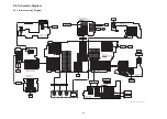
Страница 53: ...FOCUS MOTOR OIS Analog Analog Analog Analog Analog Analog IC6301 GYRO SENSOR CLK13M CLK74M CLK12M IC3402 NAND FLASH ROM 512Mbit IC851 EVF COLOR DRIVER COLOR LCD PANEL COLOR EVF PANEL IC3401 MPEG CODEC UNI PHIER XP IC3701 AVIO IC2006 SYSTEM CONTROL CAMERA MICROCOMPUTER IC1001 POWER CIRCUIT IC2304 RTC IC2002 EEPROM NOTE VIDEO SIGNAL AUDIO SIGNAL CLK or CONTROL LINE IC301 CAMERA DSP LUPINAS X2301 32 ...

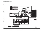
Страница 54: ... 25 26 27 28 29 30 TRIG D GND 2 1 P7002 XENON XENON 2 1 P7001 FLASH 15 14 13 12 11 10 9 8 7 6 5 4 3 2 1 S HDD G SCL IGBT GND BUS24 SDCMD D GND CLK49 SDCA A D GND S HDD G SDA BUS24 SDAT1 BUS24 SDAT0 BUS24 SDAT3 BUS24 SDAT2 AV GND G VOUT G HDYOUT G LOUT FLASH P C B COMPONENT SIDE FP904 GND GND VDD VCOML SDO SCL DB0 DB2 DB4 DB6 HSYNC DCLK VREG C13M DDVDH C11P C12P VCC2 C22P C21P VGL1 2 4 6 8 10 12 14...

Страница 55: ...DKB000015 Q3901 L3351 L7001 G1C470MA0249 CHARGE CHARGE CHAEND CHAEND TRIGEND TRIGEND BUS24_SDTA2 BUS24_SDTA2 BUS24_SDTA3 BUS24_SDTA3 BUS24_SDTA0 BUS24_SDTA0 CLK24_SDCMDA CLK24_SDCMDA BUS24_SDTA1 BUS24_SDTA1 PW_SD3R2V_1 BUS24_SDTBAA BUS24_SDTA0A BUS24_SDTA2A CLK24_SDCMDAA BUS24_SDTA3A PW_3R2V G_VOUT_JK G_HDYOUT_JK G_LOUT_JK G_ROUT_JK PLUGIN_L_JK G_PBOUT_JK G_PROUT_JK G_VOUT2 G_HDYOUT2 G_PBOUT2 G_PR...

Страница 56: ...1 K2HC104B0047 4 2 3 5 6 1 JK4902 K2HC106E0007 1 5 6 3 2 4 G1 G2 7 8 FP6400 K1MY08BA0370 1 5 6 3 2 4 G1 G2 FP6402 K1MY06BA0370 QR6401 B1GBCFJK0001 B1ABDF000017 Q4901 B1ABDF000017 Q4903 Q4907 B1ABDF000017 Q4908 B1ABDF000017 G_EXTMICL G_EXTMICL G_EXTMICR G_EXTMICR TALLY_LED S_REMO_R2R LIGHT_ON_H MFL1 MFL1 HP_DET_L HP_DET_L G_HPL G_HPL G_HPR G_HPR EXTMIC_L EXTMIC_L LENSBA_OPEN LENSBA_OPEN LENSBA_MT_B...

Страница 57: ... 18 20 15 17 16 G1 G2 K1MY20BA0370 FP802 PW_LCD8R5V CLK2_EVFCKH2 CLK2_EVFCKH1 PW_EVFBL5V PW_EVF3V G_BOUT G_ROUT G_GOUT PSIG COM COM VSSG HCK1 HCK2 HST VDD VSS RGT NRW DWN REF XSTB VST VCK ENB ENB PCG BLUE RED GREEN 0 3mm TO EVF PANEL R_OUT G_OUT B_OUT DSD DSG CKH2 PW_LCD8R5V PW_LCD8R5V STH PW_EVF3V CKV1 STV CKH1 D_GND D_GND D_GND D_GND PW_EVFBL5V PW_EVFBL5V 0 5mm SHITA TO BATT_CATCHER 2SC6054J0L M...

Страница 58: ...900 22 1 2 3 G1 4 G2 K1MY04BA0370 FP4804 RL4801 1 9 7 5 3 2 4 6 8 14 11 12 10 13 19 18 21 20 15 17 16 G1 G2 K1MN21AA0035 FP4802 B1ABDF000017 Q4801 B6401 ML 614S ZTK 1 5 6 3 2 4 G1 G2 7 8 FP4801 K1MY08BA0370 1 9 7 5 3 2 4 6 8 11 12 10 G1 G2 K1MY12BA0370 FP4803 LI_BATT VTR_KEY_5 VTR_KEY_5 VTR_KEY_5 GND GND GND GND GND GND GND GND TO ECM TO CAM_FUNC_PCB STANDBY_LED STANDBY_LED LED_GND ZOOMAD ZOOMAD T...

Страница 59: ...1 VRT0158 18 VA6702 VRT0158 18 1 5 6 3 2 4 G1 G2 K1MY06BA0370 FP6701 R6704 6800 R6703 6800 100 R6701 100 R6702 SE_GND SE_GND MFL1 MFVCC MFL2 MF SENSOR TO FRONT NC HDC HS700 MF SENS Schematic Diagram 10 9 8 7 6 5 4 3 2 1 G F E D C B A S4 6 MF SENS Schematic Diagram ...

Страница 60: ...K27_EVF BUS13_EVFYC0 BUS13_EVFYC0 G_GYROP G_GYROP G_GYRO_REF G_GYRO_REF PW_EVF1R8V G_GYROY G_GYROY SP SP SP SP FAN_FG FAN_FG PW_FAN5V PW_FAN5V KEYIN3 KEYIN3 POWER_SW POWER_SW PW_GYRO3V GYRO_GND PW_3R2V PW_REG3V TO MAIN TO MAIN 25 25 TO EVF MAIN_PCB 1pin T T D D D D D 1 50 50 16 DATA5 15 DATA6 DATA3 HSYNC VSYNC CLKIN DATA7 DATA4 ENB1 VDD1 2 85V VDD1 2 85V VDD1 2 85V VDD1 2 85V DGND DGND DGND DGND R...

Страница 61: ...00003 S_DO_LCD S_CLK_LCD S_CS_LCD BUS9_LCDYC0 BUS9_LCDYC1 BUS9_LCDYC2 BUS9_LCDYC4 BUS9_LCDYC5 BUS9_LCDYC6 BUS9_LCDYC7 CLK18_LCD BUS9_LCD_V BUS9_LCD_H BUS9_LCDYC3 E_KEYIN6 PW_LCDBL_L PW_LCDBL_H S_CK_SEL1_TP S_CK_SEL1_TP PW_REG3V PW_REG3V PW_REG1R8V S_T2S_X_TPNL S_T2S_X_TPNL S_S2T_Y_TPNL S_S2T_Y_TPNL S_CS_SEL2_TP S_CS_SEL2_TP C21P C21M C22M VCOML IOVCC VCOMH VGL2 VCC1 VDD VSYNC HSYNC DDVDH C22P C11M...

Страница 62: ...UT_B G_MIC_OUT_C G_MIC_OUT_C G_MIC_OUT_F G_MIC_OUT_F G_MIC_OUT_L G_MIC_OUT_L MIC_GND MIC_GND MIC_GND MIC_GND GND GND ZOOMAD ZOOMAD AVREF AVREF DISK_ACCESS_LED DISK_ACCESS_LED STANDBY_LED STANDBY_LED POWER_LED POWER_LED PW_LIBATT PW_LIBATT PW_LIBATT VTR_KEY_5 VTR_KEY_5 VTR_KEY_1 VTR_KEY_1 PHOTO_SW PHOTO_SW VTR_KEY_4 VTR_KEY_4 L 2 6 L 2 6 S 1 4 L 0 2 TO MAIN PS6002 HDC HS700 MIC AMP FPC Schematic Di...

Страница 63: ...FP6501 K1MN08A00072 1 3 2 4 K0F111A00589 S6501 1 3 2 4 K0F111A00589 S6502 TO FAN PW_FAN5V PW_FAN5V D_GND D_GND D_GND FAN_FG SPOUT1 SPOUT1 SPOUT2 SPOUT2 TO BATT_CATCHER TO SPEAKER 1 SP1 8 POWER_SW 1 2 3 TOP VIEW POWER ON OFF FUN_FG E_KEYIN3 POWER_SW 6 0 P HDC HS700 Side R Schematic Diagram 10 9 8 7 6 5 4 3 2 1 G F E D C B A HDC HS700 CAM FUNC FPC Schematic Diagram S4 10 CAM FUNC FPC Schematic Diagr...

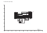
Страница 64: ...4 3 2 1 Q7005 R3901 R3902 R3903 R3904 R3905 R3908 R3909 R3910 R3911 R3912 R3913 R3914 R7011 R7015 RL7001 RL7002 RX3901 TL7001 TL7002 VA3901 C3351 CH3351 10 9 8 7 6 5 4 3 2 1 IC3351 R3351 L3351 C3352 LB3901 HDC HS700 Strobe P C B Component Side 10 9 8 7 6 5 4 3 2 1 G F E D C B A Component Side S5 Print Circuit Board S5 1 Strobe P C B S5 1 1 Strobe P C B Component Side ...

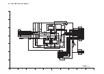
Страница 65: ...01 1 5 6 10 IC7001 L7001 LB3301 LB3302 LB3303 LB3304 LB3305 LB3306 2 1 P7001 R3311 R3312 R3313 R3314 R3315 R3907 R7001 R7002 R7003 R7004 R7006 R7007 7098 R7099 4 3 2 1 T7001 MK1 MK2 12 10 5 1 JK3301 HDC HS700 Strobe P C B Foil Side 10 9 8 7 6 5 4 3 2 1 G F E D C B A Foil Side S5 1 2 Strobe P C B Foil Side ...

Страница 66: ... R4923 R4924 R6402 R6412 R6413 R6416 RL4811 VA4901 R6403 VA4902 C4922 R4907 C6402 LB4924 C4913 R4901 R4911 R4909 e Q4901 R4910 C4921 C4902 R4905 C4903 R4925 R4915 R4908 C4923 MK8 MK7 MK6 MK5 C4910 C6401 C6405 CL6408 CL6409 D 6 4 0 1 7 6 5 4 3 2 1 8 I R 6 4 0 1 LB4928 LB4929 e QR6401 R4920 R6417 D 6 4 0 2 VA6402 VA6401 1 2 3 4 5 6 JK4902 5 3 2 1 J K 4 9 0 1 HDC HS700 Front P C B 10 9 8 7 6 5 4 3 2 ...

Страница 67: ...8 1 3 R 4 8 1 4 R4815 R4817 C4813 R806 R805 R804 R802 R801 e Q801 D804 D803 D802 D801 C803 C802 MK6 MK7 MK8 C801 R803 MK5 MK8 MK7 C4803 C4804 C4805 C4807 C4811 C4812 C4814 C4816 C4817 20 15 10 5 2 1 21 FP4802 R4802 R4803 R4804 R4805 R4808 R4809 R4810 R4812 R4818 R6405 1 2 ZB6401 R4801 C4815 RL4801 R4816 e Q4801 MK5 MK6 HDC HS700 MIC AMP P C B HDC HS700 EVF B L P C B 10 9 8 7 6 5 4 3 2 1 G F E D C ...

Страница 68: ...23 FP6301 1 5 8 FP6302 1 5 10 15 16 17 20 25 30 32 33 35 40 45 48 49 50 55 60 64 IC851 18 17 16 15 14 13 12 11 10 9 8 7 6 5 4 3 2 1 IC6301 1 2 3 4 5 IC6302 L6305 R851 R852 R853 R854 R6301 VA851 VA6751 50 45 26 25 5 1 40 10 35 15 20 30 PP601 C853 C852 MK2 MK4 MK3 MK1 1 6 5 F P 6 7 0 1 R6701 R6702 R6703 R6704 VA6701 VA6702 4 3 2 1 Q6701 4 3 2 1 Q6702 HDC HS700 BATT_Catcher P C B HDC HS700 MF SENS P ...

Страница 69: ...S 19 MK6 MK5 MK7 MK8 D902 D903 D904 D905 HDC HS700 Monitor P C B Component Side 10 9 8 7 6 5 4 3 2 1 G F E D C B A Component Side S5 7 Monitor P C B S5 7 1 Monitor P C B Component Side ...

Страница 70: ...2 C903 C904 C905 C906 C907 C908 C909 C910 C911 C912 C913 C914 C915 C916 C917 C918 C919 CH901 CH902 CH903 CH904 CH905 CH906 CH907 D906 D907 15 10 5 1 16 FP901 10 5 1 12 FP902 41 40 35 30 25 20 15 10 5 2 1 FP904 4 3 2 1 FP905 R506 R507 R901 4 3 2 1 FP903 D901 VA501 VA502 VA503 VA504 HDC HS700 Monitor P C B Foil Side S5 7 2 Monitor P C B Foil Side ...

Страница 71: ...MIC AMP FPC P C B S5 9 CAM FUNC FPC P C B FT6501 11 15 20 1 5 10 PP6003 MK1 MK2 4 3 2 1 S6601 FT6501 Foil Side 10 9 8 7 6 5 4 3 2 1 G F E D C B A HDC HS700 MIC AMP FPC P C B Foil Side HDC HS700 CAM FUNC FPC P C B ...

Страница 72: ... 22 MK3 MK4 MK2 MK1 1 3 PS6501 1 5 2 8 7 FP6501 MK5 MK6 MK8 MK7 4 3 2 1 S6501 4 3 2 1 S6502 1 2 P6501 HDC HS700 Side R P C B 10 9 8 7 6 5 4 3 2 1 G F E D C B A Foil Side Component Side S5 10 Side R P C B ...

Страница 73: ...tive Devices refer to PREVENTION OF ELECTROSTATIC DISCHARGE ESD TO ELECTROSTATICALLY SENSITIVE ES DEVICES section 1 Be sure to make your orders of replacement parts according to this list 2 IMPORTANT SAFETY NOTICE of this assembly in production it will no longer be available ...

Страница 74: ...32 T CAPACITOR CH 6 3V 22U 1 C7002 ECJ0EC1H150J C CAPACITOR CH 50V 15P 1 C4913 F1H0J475A010 C CAPACITOR CH 6 3V 4 7U 1 C7003 F1J1A106A043 C CAPACITOR CH 10V 10U 1 C4923 F1G0J1050007 C CAPACITOR CH 6 3V 1U 1 C7005 F1K2E4730005 C CAPACITOR 250V 0 047U 1 C6401 F1J0J106A049 C CAPACITOR CH 6 3V 10U 1 C7010 F1K2E223A004 C CAPACITOR 250V 0 022U 1 C6405 F1G1A104A012 C CAPACITOR CH 10V 0 1U 1 D7002 B0ECGP0...

Страница 75: ...70 CONNECTOR 20P 1 R6701 ERJ2GEJ101 M RESISTOR CH 1 10W 100 1 Q801 B1ABDF000017 TRANSISTOR 1 E S D R6702 ERJ2GEJ101 M RESISTOR CH 1 10W 100 1 R6703 ERJ2GEJ332 M RESISTOR CH 1 16W 3 3K 1 R801 ERJ2RHD562 M RESISTOR CH 1 16W 5 6K 1 R6704 ERJ2GEJ332 M RESISTOR CH 1 16W 3 3K 1 R802 ERJ2RKD910 M RESISTOR CH 1 16W 91 1 R803 ERJ2GEJ105 M RESISTOR CH 1 10W 1M 1 R804 ERJ2RHD122 M RESISTOR CH 1 16W 1 2K 1 R8...

Страница 76: ...CAPACITOR CH 6 3V 1U 1 C908 ECJ1VB1A105K C CAPACITOR CH 10V 1U 1 C909 F1G0J1050007 C CAPACITOR CH 6 3V 1U 1 C910 ECJ1VB1A105K C CAPACITOR CH 10V 1U 1 C911 F1G0J1050007 C CAPACITOR CH 6 3V 1U 1 C912 F1H1E105A116 C CAPACITOR CH 25V 1U 1 C913 F1H1E105A116 C CAPACITOR CH 25V 1U 1 C914 F1G0J1050007 C CAPACITOR CH 6 3V 1U 1 C915 F1G0J1050007 C CAPACITOR CH 6 3V 1U 1 C916 F1G0J1050007 C CAPACITOR CH 6 3V...

Страница 77: ...IC AMP FPC UNIT 1 RTL E S D 81 VYK3Q52 SIDE CASE L UNIT 1 82 VYK3Q31 SENSOR COVER UNIT 1 85 VEP20C84A FRONT PCB UNIT 1 RTL E S D 91 VMP8492 SHOE ANGLE 1 92 VYK3Q72 HDD GND CASE UNIT 1 93 VGQ9672 GASKET 1 95 VMG1922 HDD CUSHION 1 96 VMG1922 HDD CUSHION 1 98 RFKV0224HDKT HDD 1 99 VGQ0M74 CUSHION 1 100 VGQ0M76 SHEET 1 B14 VHD1814 SCREW 1 B15 VHD1814 SCREW 1 B16 VHD1814 SCREW 1 B17 VHD1814 SCREW 1 B18...

Страница 78: ...B EC EE GC GN 16 VYK3X24 SIDE CASE R UNIT 1 P PC PU GT 17 L0AA01A00050 SPEAKER 1 18 VMP9589 SP ANGLE 1 19 L6FAG99D0020 FAN MOTOR 1 20 VMG1928 FAN DAMPER 1 21 VEP06G50A SIDE R OP PCB UNIT 1 RTL E S D 22 K0RE00600006 SWITCH UNIT 1 83 VKM8271 SR COVER 1 97 VGQ0L69 POWER IC HEAT RADIATION S 1 B1 XQN16 BJ4FN SCREW 1 B2 XQN16 BJ4FN SCREW 1 B9 XQN16 BJ4FN SCREW 1 B10 XQN16 BJ4FN SCREW 1 B49 VHD1907 SCREW...

Страница 79: ...E13 EVF ANGLE KNOB 1 66 VGQ0D02 PRISM REINFORCEMENT PIECE 1 67 VGL1340 POLARIZE LENS PLATE 1 68 VGQ0D01 LCD HOLD PIECE 1 69 L5BDDXH00033 LCD 1 70 VGQ0D03 LCD REINFORCEMENT PIECE 1 71 VGL1341 EVF B L POLARIZE LENS PLATE 1 72 VGL1304 EVF DIFFUSION SHEET 1 73 VGQ0D04 B L PIECE 1 74 VEP29224A EVF BL PCB UNIT 1 RTL E S D 75 VGQ0K40 EVF SLIDE CASE 1 76 VMP9583 EVF SLIDE FRAME 1 77 VEP29225A EVF FPC UNIT...

Страница 80: ...MONITOR PCB UNIT 1 RTL E S D 23 VYK3Q66 LCD CASE T UNIT 1 24 VYK3U03 PANEL UNIT 1 25 VGQ0K48 LIGHTING PLATE HOLDER 1 26 VGL1322 PRISM SHEET A 1 27 VGL1323 PRISM SHEET B 1 28 VGL1324 DIFFUSION SHEET 1 29 VKW3442 LIGHT GUIDE PLATE 1 30 VGL1325 REFLECTION SHEET 1 31 VMP9590 LCD FRAME 1 B7 VHD1688 SCREW 1 B8 VHD1688 SCREW 1 S 30 ...

Страница 81: ...E S 1 212 VDW1995 MASTER FLANGE COVER 1 213 VDL1900 OPTICAL FILTER 1 214 VXP3391 2ND LENS FRAME MOVE UNIT 1 215 VMB4358 2ND LENS FRAME MOVE UNIT SP 1 216 VDW1989 BODY UNIT 1 217 VXQ1856 OIS UNIT 1 218 VXP3394 4TH LENS FRAME MOVE UNIT 1 219 VXQ1855 1ST LENS FRAME UNIT 1 B201 VHD2072 SCREW 1 B202 VHD2072 SCREW 1 B203 VHD2072 SCREW 1 B204 VHD2072 SCREW 1 B205 VHD2072 SCREW 1 B206 VHD2072 SCREW 1 B207...

Страница 82: ...86 OPERATING INSTRUCTIONS 1 EC 310 VQT2M87 OPERATING INSTRUCTIONS 1 EC 310 VQT2M94 OPERATING INSTRUCTIONS 1 EE RUSSIAN 310 VQT2M95 OPERATING INSTRUCTIONS 1 EE UKRAINIAN 310 VQT2M75 OPERATING INSTRUCTIONS 1 P PC ENGLISH 310 VQT2M76 OPERATING INSTRUCTIONS 1 PC CANADIAN FRENCH 310 VQT2M77 OPERATING INSTRUCTIONS 1 PU ENGLISH 310 VQT2M78 OPERATING INSTRUCTIONS 1 PU 310 VQT2M91 OPERATING INSTRUCTIONS 1 ...

Страница 83: ...B70 B69 B93 B68 B66 95 98 8 96 B57 B48 B92 B47 92 93 B91 a 47 B30 B31 B32 B33 79 78 51 48 B71 B34 B35 B36 B37 45 46 B29 B26 B28 B27 B94 B95 B96 91 37 B18 B20 B19 85 34 B75 B67 82 38 39 36 35 B17 B16 B15 B14 33 40 43 42 B21 44 99 49 50 53 54 57 55 56 52 100 41 ...

Страница 84: ...S7 2 Frame and Casing Section 2 S 34 12 B50 B58 B51 11 B60 B78 B80 B81 B49 13 3 14 15 B1 B2 B54 B53 B52 10 1 B55 B56 2 4 97 9 a B9 B10 18 17 5 B79 B61 B62 B72 B73 B74 B65 B64 B63 21 19 20 16 83 B59 ...

Страница 85: ...S7 3 EVF Section S 35 B23 59 B22 58 60 61 62 63 65 64 66 67 68 69 70 72 71 73 74 75 76 77 B24 ...

Страница 86: ...S7 4 LCD Section S 36 27 28 29 26 30 32 23 31 25 22 B7 B8 24 ...

Страница 87: ...S7 5 Camera Lens Section S 37 B215 201 B214 213 215 B212 B213 212 206 207 218 210 211 B209 B210 B211 217 208 209 B205 B204 204 216 214 219 B208 B207 B206 205 B201 B202 B203 203 ...

Страница 88: ...S7 6 Packing Parts and Accessories Section S 38 309 323 308 310 316 HDC HS700P PC PU GT GK 314 HDC HS700EG EP EF EC EE GC 315 318 HDC HS700GN HDC HS700EB GC 307 302 313 312 301 303 311 306 321 305 ...

Отзывы: