


58
9.1.3.
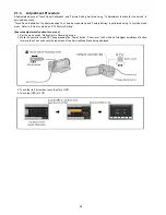
Adjustment Procedure
All adjustments except “Touch Panel Calibration” and “Factory Setting” performs using “14 Adjustment function for the service” in
service mode menu.
“Touch Panel Calibration” is performed using 16 of service mode menu and “Factory Setting” is performed using 1 of service mode
menu. Refer to “6 Service mode” and “10 Factory Setting”.
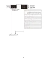
[Execute adjustment function for service]
1. Set the mode switch “Motion Picture Recording” mode.
2. While the power is turned OFF, keep pressing the “Power” button, “Zoom lever” to W side and “intelligent auto/Manual” button
for more than 3 seconds until the top screen of the Service Mode Menu being displayed.
3. Touch the 3 times then touch the [14] of LCD.
4. Touch the [YES] of LCD.
Содержание HC-X910GC
Страница 10: ...10 3 5 Formatting ...
Страница 12: ...12 4 Specifications 4 1 For NTSC Areas ...
Страница 13: ...13 ...
Страница 14: ...14 ...
Страница 15: ...15 ...
Страница 16: ...16 ...
Страница 17: ...17 4 2 For PAL Areas ...
Страница 18: ...18 ...
Страница 19: ...19 ...
Страница 20: ...20 ...
Страница 21: ...21 ...
Страница 36: ...36 8 2 PCB Location ...
Страница 39: ...39 8 3 1 Removal of the Side Case L Unit Fig D1 Fig D2 ...
Страница 40: ...40 8 3 2 Removal of the SD OP P C B Cover Board Unit Fig D3 Fig D4 ...
Страница 41: ...41 8 3 3 Removal of the ESD P C B HC X920M only Fig D5 8 3 4 Removal of the Top Case Unit Fig D6 ...
Страница 42: ...42 Fig D7 8 3 5 Removal of the Front Case Unit Fig D8 ...
Страница 44: ...44 Fig D11 Fig D12 ...
Страница 45: ...45 8 3 8 Removal of the Fan Motor Fig D13 8 3 9 Removal of the LCD Panel Unit Monitor P C B Fig D14 Fig D15 ...
Страница 46: ...46 Fig D16 Fig D17 ...
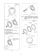
Страница 48: ...48 Fig D22 Fig D23 8 3 13 Removal of the MF Piece MF Ring MF Holl Detect FPC and MF Front Case Fig D24 ...
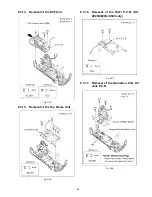
Страница 50: ...50 Fig D29 8 3 18 Removal of the Mic Amp P C B Fig D30 8 3 19 Removal of the CAM Func FPC Fig D31 ...
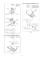
Страница 52: ...52 Fig D35 8 3 23 Removal of the EVF Slide Case EVF EXT P C B Fig D36 ...
Страница 53: ...53 Fig D37 8 3 24 Removal of the LCD Fig D38 8 3 25 Removal of the EVF Lens A B C Fig D39 ...
Страница 56: ...56 Level Shot Adjutment Chart ...
Страница 57: ...57 9 1 2 Adjustment Items Adjustment item as follows ...
Страница 60: ...60 ...
Страница 61: ...61 ...
Страница 62: ...62 ...
Страница 63: ...63 ...
Страница 64: ...64 ...
Страница 65: ...65 ...
Страница 66: ...66 ...


