


27
6.1.
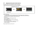
Built-in Memory Self Check Execution (HC-X920M only)
Touch the [ 3 ] of LCD, select Built-in memory self check execution.
Operation specifications
Indication contents
• Built-in memory self check result display
Display the Built-in memory self check execution.
Displays other than “OK” are abnormalities of Built-in memory.
Touch the [ BAK ] of LCD to end the service mode, and then POWER OFF.
6.2.
Lock Search History Indication
Touch the [ 4 ] of LCD, select Lock search history indication.
Operation specifications
Indication contents
• Lock search history indication
Display the camera system error cord for three histories saved in EEPROM.
• The error cord contents which are displayed
Touch the [ BAK ] of LCD to end the service mode, and then POWER OFF.
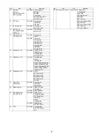
Error code
Function
51
Focus control is abnormal
52
Zoom control is abnormal
53
OIS lens control is abnormal
54
Zoom control is abnormal (2)
71
Lens cover open/close is abnormal
72
Cooling fan is abnormal
73
High temperature is abnormal
Содержание HC-X910GC
Страница 10: ...10 3 5 Formatting ...
Страница 12: ...12 4 Specifications 4 1 For NTSC Areas ...
Страница 13: ...13 ...
Страница 14: ...14 ...
Страница 15: ...15 ...
Страница 16: ...16 ...
Страница 17: ...17 4 2 For PAL Areas ...
Страница 18: ...18 ...
Страница 19: ...19 ...
Страница 20: ...20 ...
Страница 21: ...21 ...
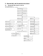
Страница 36: ...36 8 2 PCB Location ...
Страница 39: ...39 8 3 1 Removal of the Side Case L Unit Fig D1 Fig D2 ...
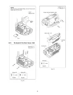
Страница 40: ...40 8 3 2 Removal of the SD OP P C B Cover Board Unit Fig D3 Fig D4 ...
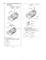
Страница 41: ...41 8 3 3 Removal of the ESD P C B HC X920M only Fig D5 8 3 4 Removal of the Top Case Unit Fig D6 ...
Страница 42: ...42 Fig D7 8 3 5 Removal of the Front Case Unit Fig D8 ...
Страница 44: ...44 Fig D11 Fig D12 ...
Страница 45: ...45 8 3 8 Removal of the Fan Motor Fig D13 8 3 9 Removal of the LCD Panel Unit Monitor P C B Fig D14 Fig D15 ...
Страница 46: ...46 Fig D16 Fig D17 ...
Страница 48: ...48 Fig D22 Fig D23 8 3 13 Removal of the MF Piece MF Ring MF Holl Detect FPC and MF Front Case Fig D24 ...
Страница 50: ...50 Fig D29 8 3 18 Removal of the Mic Amp P C B Fig D30 8 3 19 Removal of the CAM Func FPC Fig D31 ...
Страница 52: ...52 Fig D35 8 3 23 Removal of the EVF Slide Case EVF EXT P C B Fig D36 ...
Страница 53: ...53 Fig D37 8 3 24 Removal of the LCD Fig D38 8 3 25 Removal of the EVF Lens A B C Fig D39 ...
Страница 56: ...56 Level Shot Adjutment Chart ...
Страница 57: ...57 9 1 2 Adjustment Items Adjustment item as follows ...
Страница 60: ...60 ...
Страница 61: ...61 ...
Страница 62: ...62 ...
Страница 63: ...63 ...
Страница 64: ...64 ...
Страница 65: ...65 ...
Страница 66: ...66 ...


