3. TROUBLESHOOTING GUIDE
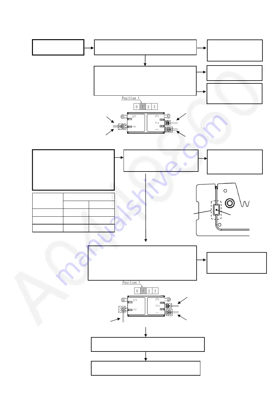
Refer to WIRING CONNECTION DIAGRAM.
Replace MOTOR HEATER ASSEMBLY
< TROUBLE >
< CHECK >
< REMEDY >
Main body is
not operated
<CHECK POWER CORD>
Check the conductivity of power cord
<CHECK MAIN SWITCH>
Check the conductivity between the terminal 1
and 4 by setting
the MAIN SWITCH to Position 1
(Figure 1)
Replace the
MAIN SWITCH
Replace the
MOTOR HEATER
ASSEMBLY
NG
OK
NG
OK
Replace the
MOTOR HEATER
ASSEMBLY
Lead Wire (Yellow)
Lead Wire (Red)
Lead Wire (Gray)
Lead Wire (Orange)
Main Switch
Figure 1
Control point
Thermistor must
be placed at
the center of hole
Thermistor
<CHECK TEMPERATURE SWITCH>
Check the conductivity between the terminal 1
and 4 by setting
the TEMPERATURE SWITCH to Position 1
(Figure 4)
Replace the
TEMPERATURE SWITCH
NG
Figure 4
Replace PRINTED CIRCUIT ASSEMBLY
OK
Figure 2
For EH-NE82 and 84 only
Advance heat protection mode is not
operated or not operated follow spec
(Figure 2)
*Air keep switching between hot and cold
<
CHECK THERMISTOR>
Check the position of thermistor
(Figure 3)
Adjust the position
of thermistor follow
control point
NG
OK
Figure 3
Environmental
Interval time (sec)
29.1
º
C or more 2.0 ~ 4.5
5.0 ~ 8.0
temperature
Hot air
Cold air
23.9
º
C or less
3.0 ~ 8.0
2.0 ~ 4.5
24 ~ 29
º
C
2.0 ~ 6.0
2.0 ~ 5.5
*Check interval time after operate on this mode for 30 sec
OK
Lead Wire (Black)
Lead Wire (Brown)
Lead Wire (Orange)
Temperature switch
Содержание EH-NE84
Страница 12: ...5 Wiring Connection Diagram ...


