- 28 -
Service adjustments (electronic controls, cont.)
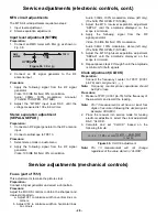
MTS circuit adjustments
The MTS circuit adjustments require two steps:
1.
Input level adjustment.
2.
Stereo separation adjustment.
Input level adjustment (MTSIN)
Preparation:
1.
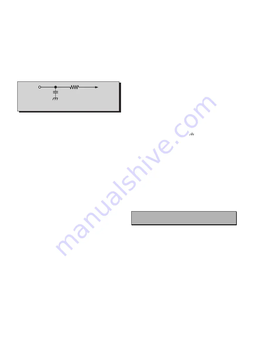
Connect an RMS meter with filter jig as shown in
Fig. 38.
2.
Connect an RF signal generator to the RF
antenna input.
Procedure:
1.
Apply the following signal from the RF signal
generator:
Video: 100 IRE flat field, 30% modulation.
Audio:
300Hz,
100%
modulation,
monaural
(70 ±5dB, 75
Ω
OPEN, P/S 10dB).
2.
Adjust the “MTSIN” input level DAC until the
voltage measured is 106 ± 6.0mV rms.
Stereo separation adjustment
(SEPAL & SEPAH)
Preparation:
1.
Connect an RF signal generator to the RF antenna
input.
2.
Connect oscilloscope to TPE10.
Procedure:
1.
Select stereo mode in audio menu
2.
Apply the following signal from the RF signal
generator:
Video: 100 IRE flat field, 30% modulation.
Audio: 300Hz, 100% modulation, stereo (left only)
(70 ±5dB, 75
Ω
OPEN, P/S 10dB).
3.
Adjust the MTS low-level separation adjustment
“SEPAL” until the amplitude displayed on the
scope is minimum.
4.
Apply
the
following
signal
from
the
RF
signal generator:
Video: 100 IRE flat field, 30% modulation.
Audio: 3KHz, 100% modulation, stereo (left only)
(70 ±5dB, 75
Ω
OPEN, P/S 10dB).
5.
Adjust the MTS high-level separation adjustment
“SEPAH” until the amplitude displayed on the
scope is minimum.
6.
Repeat above steps 2 through 5 until the amplitude
is minimum for both signals.
Clock adjustment (CLOCK)
Preparation:
Connect the frequency counter to TP017 (IC001
pin-79) and cold ground (
).
Note:
Frequency counter probe capacitance should
be 8pF or less.
Procedure:
1.
Measure TP017 (IC001 pin-79) for the frequency of
the waveform and record the reading.
Note:
Pin 13 measurement must have at least four
digits of resolution following the decimal point.
Example: 000.0000
2.
Place the receiver into service mode for making
electronic adjustment, select the clock adjustment
DAC “CLOCK”.
3.
Calculate
and
set
“CLOCK”
based
on
the
following formula:
Note:
Pin
13
measurement
will
not
change
regardless of the value stored in “CLOCK”.
Service adjustments (mechanical controls)
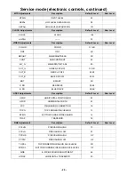
Focus (part of T551)
This adjustment is to make the picture clear
Preparation:
Connect a Signal generator and select a dot pattern.
Procedure:
Adjust the FOCUS controls to obtain the sharpest and
clearest dot pattern.
a. Adjust VF1 to minimize width on vertical lines on
corners.
b. Adjust VF2 to minimize width on horizontal lines
on corners.
10k
4700p
TPE11
RMS
METER
Figure 38. Filter jig
CLOCK
128
450000
732.4220
pin
79
Hz
[
]
Ð
732.4220
-------------------------------------------------------------
+
=
Figure 39. CLOCK adjustment
-
Содержание CT-32SC13-1G
Страница 63: ... 50 A Board ...
Страница 65: ... 52 ERJ6GEYJ183V NP2AH037AC ERENCES A Board ...
Страница 66: ... 53 A Board ...
Страница 69: ... 56 D Board ...
Страница 70: ... 57 D Board ...
Страница 71: ... 58 D Board ...
Страница 74: ... 61 notes NOTES ...
Страница 75: ... 62 G Board ...
Страница 76: ... 63 G Board ...
Страница 77: ... 64 G Board ...
Страница 79: ... 66 L Board ...
Страница 80: ... 67 L Board ...
Страница 81: ... 68 A PCB ...
Страница 82: ... 69 A PCB ...
Страница 83: ... 70 D PCB ...
Страница 84: ... 71 D PCB ...
Страница 85: ... 72 G PCB ...
Страница 86: ... 73 G PCB ...
Страница 87: ... 74 L PCB ...
Страница 88: ... 75 notes NOTES ...

