
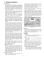


IMPORTANT
To protect against possible damage to the solid state
devices due to arching or static discharge, make certain
that all ground wires and CRT DAG wire are securely
connected.
CAUTION
The power supply circuit is above earth ground and the
chassis cannot be polarized. Use an isolation transformer
when servicing the receiver to avoid damage to the test
equipment or to the chassis. Connect the test equipment to
the proper ground (hot) or (cold) when servicing, or
incorrect voltages will be measured.
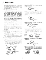
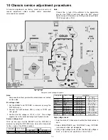
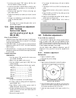
2.1. X-Ray Protection Circuit Check
& Adjustments
This test must be performed as final check before the receiver
is returned to the customer. If voltages are out of tolerance,
immediate service and correction is required to insure safe
operation and to prevent the possibility of premature
component failure.
Equipment:
1. Isolation transformer.
2. High voltage meter.
3. D.C. Ammeter
4. Short jumper.
5. HHS jig (See figure below).
Diode Connection Jumper.
Preparation:
1. Make sure the receiver is turned off.
2. Connect the receiver to an isolation transformer.
3. Connect the ammeter serial from the flyback anode lead
to the picture tube anode socket.
4. Prepare short jumper and HHS jig.
Procedure:
1. Connect the short jumper between TPD16 & TPD17.
2. Connect the jumper diode between TPD14 and TPD15
(anode connected to TPD15 and cathode to TPD14).
3. Apply 75VAC to AC input of isolation transformer.
4. Turn the receiver on.
5. Apply a monoscope pattern.
6. Set customer picture and brightness controls to the
minimum.
7. Set current within 50µA to 100µA by changing the
picture and bright controls.
8. Slowly increase AC voltage at the input of the isolation
transformer and confirm HHS voltage measure
34.5kV
.
9. Turn power off and remove jigs.
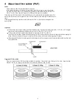
3 EEPROM replacement
If a new EEPROM integrated circuit is replaced for servicing,
follow the next procedure once that the memory is properly
assembled:
1. Enter to service mode.
2. Turn the TV set ON.
3. Once inside service mode the first image that appears on-
screen is the ID1 register with the respective address value
(FF) like the image below.
Note:
All 3 registers (ID1,ID2,ID3) should appear with FF
values if a new EEPROM is assembled.
4. With “VOL” keys adjust the correct value according with the
service adjustment table (see “Service Mode” section).
5. Change to the next ID switch register with “CH” keys and
repeat the same procedure as step 4.
6. When replacing a new EEPROM be sure to set the correct
ID switch values for each model.
7. Once that all 3 registers are set with the correct address
value, perform all of the remaining adjustments and
servicing.
IMPORTANT:
Correct ID switch configuration should be input when
replacing EEPROM for each television model, otherwise if
wrong values are configured, the television software will not
function accordingly and properly.
5
Содержание CT-27SL14 - 27" CRT TV
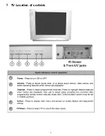
Страница 8: ...7 TV Location of controls 8 ...
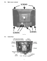
Страница 11: ...9 2 Back cover removal Back Cover 9 3 Inside View 11 ...
Страница 20: ...14 Reference for PDF colors 20 ...
Страница 21: ...15 Conductor views 21 ...
Страница 25: ...16 Block diagrams 25 ...
Страница 28: ...17 Schematics 28 ...
Страница 29: ...17 1 English schematic notes 29 ...
Страница 30: ...17 2 Notas de esquemáticos en español 30 ...
Страница 44: ...18 Parts location 44 ...
Страница 45: ...19 Parts list 19 1 Parts list notes 45 ...


